😕 My pub (Hoppe, 020-NL) is still open. 😉
So, what do you mean?
Cheers, E.
We haven't seem you for some time, I thought you holed up in Hoppe and now were thrown out.
My humour is sometimes a bit opaque, sorry...
Jan
We haven't seem you for some time, I thought you holed up in Hoppe and now were thrown out.
My humour is sometimes a bit opaque, sorry...
Jan
Hi Jan,
The reason I'm 'pretty absent' is two fold:
1. The S/N ratio of this thread is rather high.
2. I'm still working on 'DiAna', as you might know, my PC based distortion analyzer. It's a hell of a job, as everything I have to invent by myself. For example, no literature is available on the web how to write the code for a (sort of) IQ detector that calculates the amplitude, phase, offset and frequency with the same accuracy as the machine precision (i.e. with a mantissa of 64 bits!). Moreover, writing 'audio software' is especially tricky as you have to deal with tons of unexpected events (and sound cards that misbehave!).
But, when this project has finished, I hope I've more time to build amps and contribute on a more regular base in this forum .
Cheers, E.
Well you certainly set yourself a worthy task!
Maybe, when it is finished, you should write about it!
Jan
Maybe, when it is finished, you should write about it!
Jan
i.e. with a mantissa of 64 bits
corrections for General Relativity effects?
Science Magazine: Sign InHere we report the detection of
relativistic time dilation due to velocities of several
meters per second and, separately, due to a
change in height of 0.33 m by comparing two
optical clocks based on 27Al+ ions.
they only needed ~55 bits
Last edited:
Sure! In your 'Bookzine', of course.Well you certainly set yourself a worthy task!
Maybe, when it is finished, you should write about it!
Jan
BTW, maybe you could be of some help.
In the coming days I will send you a PM.
Cheers, E.
Surely you must be joking mr jcx. 😀
Admittedly, striving for 64 bits precision looks rather 'anal'. However, when the distortion is zero (theoretically) I don't like answers like -180dB or so. Zero is zero, period. So I'm only satisfied when DiAna answers <-380dB (equally to the machine precision). Anything else is just an indication of lousy programming.
Cheers, E.
PM: Writing this kind of S/W is just as 'anal' as building a sub ppm amp. 😉
Last edited:
See the ThermalTrack + TMC amp -- line #213,214. ??
[counting-down - 2 days to go]
THx-RNMarsh
[counting-down - 2 days to go]
THx-RNMarsh
Sorry Damir for various reasons I can't disclose the OPS. I am only one of the parties that has been developing the circuit.
Error correction is feedback 🙁.
If you have a REAL open loop outputstage with that kind of performance please show.
Of course. But, there, the local OPS feedback has only to take care of the OPS distortion, Not the more complex added ones of 3 stages. So can-we suppose it is more efficient ?Error correction is feedback 🙁.
An other point is this local feedback is 100% (assuming the OPS is a x1 gain stage).
Well, i have no experience of this kind of error correction, sound side. But, for sure, it is a very interesting track to explore.
Mr Cordell could tell more about his experiences on this, and the way it sound ?
The reason I designed the OPS feedback/error-correction was to make a tight loop around the OPS, reason is that I really don't see the purpose of using the input stage (and the gain of that) to correct errors occurring in the OPS. Now that my OPS relies on FB (like any other buffer) I have the option of tailoring the output impedance from slightly negative to more positive values. The error correction is based on a different approach than the HEC and Cordell Error Correction. it is simpler and more efficient.
Some amateur questions and comments on the feedback topic.
If you correct by local loop the output stage of the amplifier and have an error previously in the input section wouldn't that error be passed untouched as it would be an exact reproduction of the input to the last output section?
If you use local loops all throughout the amplifier circuit from the input section to the power section how is that superior to a one single feedback loop that encompasses the entire circuit, given that you have sufficient SR and bandwidth to have the feedback signal not affect the audio signal?
Why would there be any ultimate difference in the two approaches given the same SR and bandwidth?
The OPS will of course pass errors present in the signal that is feed to it. What I clearly see in my simulations is that a GFB loop is better with small signals and low frequencies where the two loop (No Global feedback) is significantly better at high signal levels and high frequencies. The OPS can still be included in a GFB structure.
if there was no such thing as latency and stray inductance/capacitance thru the devices, then there would be no difference. In an amplifier the signal changes status from voltage to current and back again numerous times. this transformation holds phase shifts that ultimately swamps the perfection of feedback. so in my book shorter loops with lees transformations will be better. But then that is just my physical interpretation of things.
if there was no such thing as latency and stray inductance/capacitance thru the devices, then there would be no difference. In an amplifier the signal changes status from voltage to current and back again numerous times. this transformation holds phase shifts that ultimately swamps the perfection of feedback. so in my book shorter loops with lees transformations will be better. But then that is just my physical interpretation of things.
MiiB,
Thank you for your answer. I follow all of what you are saying. The only area that I think there would be disagreement with is the latency, as I understand this the speed would be so much faster than needed for the audio portion of the circuit that this would go against feedback theory. The phase shift makes more sense in this context than the latency factor. Again this is only from the simple understanding that I have of feedback theory.
Thank you for your answer. I follow all of what you are saying. The only area that I think there would be disagreement with is the latency, as I understand this the speed would be so much faster than needed for the audio portion of the circuit that this would go against feedback theory. The phase shift makes more sense in this context than the latency factor. Again this is only from the simple understanding that I have of feedback theory.
The OPS can still be included in a GFB structure.
Could always use "split" feedback points where at low frequencies the OPS can be included in the GFB loop and at high frequencies the feedback point could be taken from the VAS.
One potential problem I can see is the loading on the VAS caused by the feedback network at high frequencies.
Of course.If you correct by local loop the output stage of the amplifier and have an error previously in the input section wouldn't that error be passed untouched ..?
Less poles in each stage's loop means less phase error, means more efficient feedback correction at HF, and better stability.If you use local loops all throughout the amplifier circuit from the input section to the power section how is that superior to a one single feedback loop that encompasses the entire circuit, given that you have sufficient SR and bandwidth to have the feedback signal not affect the audio signal?
We are at the limit, with global negative feedback and the speed of the actual devices. Most of the time, there is already a phase shift problem at 20kHz between input signal and feedback signal. To be more precise, we are limited by the added phase shifts in the open loop and have to find a compromise in bandwidth/gain. That one of the reason some prefer CFAs to LTP, more efficient at this point of view (one pole left).
Thanks Christophe for that answer. I have often thought this about the extremely complex circuits where more and more components are added chasing each and every supposed problem and now thinking about the added parasitic additions of all this extra circuitry. Simple has always seemed to be the ultimate goal in my mind in engineering if you can reach the end result you are after. It is usually an elegant simple solution that is the best end result in so many ways, KISS.
MCD99Uk, My gain setting feedback is from the VAS, I take the feedback right after the Hawksford-cascode, where I build at bridge with two resistors, there the signal is current. with full swing +/-56V I use less than 1mA for the feedback network compared to the 12mA I pull through the VAS/driverstage. this loading is pure resistive.
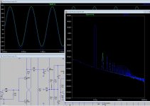
The picture shows two FFT's one from the VAS and on from the output of the amplifier. As seen on the picture the OPS adds some 2. Harmonic, where as the 3 and higher order are primarily generated in the IPS/VAS structures of the amplifier.
Harmonic Frequency Fourier Normalized Phase Normalized
Number [Hz] Component Component [degree] Phase [deg]
1 1.000e+03 3.934e+01 1.000e+00 -0.13° 0.00°
2 2.000e+03 6.913e-04 1.757e-05 -80.61° -80.47°
3 3.000e+03 2.601e-04 6.612e-06 6.41° 6.54°
4 4.000e+03 1.864e-05 4.738e-07 -2.29° -2.16°
5 5.000e+03 9.504e-06 2.416e-07 -104.57° -104.43°
6 6.000e+03 1.279e-05 3.252e-07 -13.59° -13.45°
7 7.000e+03 3.019e-06 7.676e-08 61.18° 61.32°
8 8.000e+03 8.180e-06 2.079e-07 -8.85° -8.72°
9 9.000e+03 4.787e-06 1.217e-07 68.25° 68.38°
Total Harmonic Distortion: 0.001879%
Attachments
Could always use "split" feedback points where at low frequencies the OPS can be included in the GFB loop and at high frequencies the feedback point could be taken from the VAS.
One potential problem I can see is the loading on the VAS caused by the feedback network at high frequencies.
That's basically what TMC does. At lower freqs, the OPS is in the GNFL, and at HF, the loop transfers to just around the VAS or driver stages.
With TMC you get about a 5x reduction in distortion across the audio band as a result. See Edmond Stuart s posts for a definitive explanation.
"Super KISS" seems to beat "Miibtech" 😀
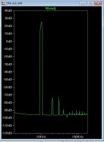
I get <.0018% (.0015) @10k/80v p-p.
CFA/Hawksford harmonics are very similar ... interesting !
Don't see any extra H2 from my properly biased EF3 ??
... Unless I "misbias" it , then H2 rises.
(below) H3 is always dominant (just like my "spooky leach") , H2 is
always cancelled.
OS
I get <.0018% (.0015) @10k/80v p-p.
CFA/Hawksford harmonics are very similar ... interesting !
Don't see any extra H2 from my properly biased EF3 ??
... Unless I "misbias" it , then H2 rises.
(below) H3 is always dominant (just like my "spooky leach") , H2 is
always cancelled.
OS
Attachments
- Home
- Amplifiers
- Solid State
- CFA Topology Audio Amplifiers