CMCL compensation
Hi Paul,
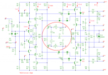
Also a CMCL needs definitely compensation, as with most loops. But that doesn't mean you always need extra components. In case of the MCP amp, the caps C3 and C4 serve a dual purpose: compensation of the global FB loop AND compensation of the common mode control loop (CMCL). As for the latter, this is achieved by a capacitive shunt between the base of Q13 respectively Q14, consisting of C3 and C4 in series (=60pF). Without these caps, the CMCL would be unstable.
Checking the loop response is quite simple, at least if you accept some minor inaccuracies*.
Just insert V1, C46, L8 & L9 (see 1st pic) and observe the response of V(u,v) / V(v1).
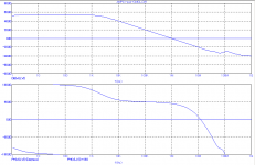
The 2nd pic shows the response. PM = 82 degrees (@1MHz) and GM = 22dB (@12MHz).
Cheers, E.
* You can do it this way because the impedance between node U and V is much lower then between the bases of Q11 and Q12.
Edmond,
Have been using the CMCL (MCP version) in some prototypes along with experimenting with your DTMC. Both ideas work well.
Does the CMCL loop itself require any specific compensation? My skills in loop analysis are not quite up to the job yet, to answer that question independently...
Paul
Hi Paul,
Also a CMCL needs definitely compensation, as with most loops. But that doesn't mean you always need extra components. In case of the MCP amp, the caps C3 and C4 serve a dual purpose: compensation of the global FB loop AND compensation of the common mode control loop (CMCL). As for the latter, this is achieved by a capacitive shunt between the base of Q13 respectively Q14, consisting of C3 and C4 in series (=60pF). Without these caps, the CMCL would be unstable.
Checking the loop response is quite simple, at least if you accept some minor inaccuracies*.
Just insert V1, C46, L8 & L9 (see 1st pic) and observe the response of V(u,v) / V(v1).
The 2nd pic shows the response. PM = 82 degrees (@1MHz) and GM = 22dB (@12MHz).
Cheers, E.
* You can do it this way because the impedance between node U and V is much lower then between the bases of Q11 and Q12.
Attachments
There is always the test instrument rental store.😎🙂
Here is an HP oscillator/generator source that was spec'ed at .0018% THD+N. With some tweaking it can do much better.... this is thru several opamps, caps and other parts selection and retuning. It can be used to test amps etc and only cost about 100-200 USD used. The down side is -- To tune it and accurately know the distortion levels requires either a ShibaSoku AD725D analyzer or an A-Precision 2722, though. Slightly higher cost: About $60K USD, new for both. However, you can copy process and then tune for best null. Even if you cant measure the generator's THD/N accurately, it will be below -100dB after the mods.
Click on picture and zoom in -- Using a Panasonic Industrial AP-7722A
View attachment 388348
Thx-RNMarsh
Hi, Jan it just Controversial Feedback Amplifier, lets not start more true CFA, 😉
@ Bonsai,
this one also has 0.0008%THD 20k but don't know how to plot its stability picturecould you help?😕
The Cordell amplifier was .0008 back in the early 1980's
Hi Paul,
Also a CMCL needs definitely compensation, as with most loops. But that doesn't mean you always need extra components. In case of the MCP amp, the caps C3 and C4 serve a dual purpose: compensation of the global FB loop AND compensation of the common mode control loop (CMCL). As for the latter, this is achieved by a capacitive shunt between the base of Q13 respectively Q14, consisting of C3 and C4 in series (=60pF). Without these caps, the CMCL would be unstable.
Checking the loop response is quite simple, at least if you accept some minor inaccuracies*.
Just insert V1, C46, L8 & L9 (see 1st pic) and observe the response of V(u,v) / V(v1).
The 2nd pic shows the response. PM = 82 degrees (@1MHz) and GM = 22dB (@12MHz).
Cheers, E.
* You can do it this way because the impedance between node U and V is much lower then between the bases of Q11 and Q12.
Hi Edmond,
Thank you for taking the time to help. You don't know how useful this information is to me.
Have just tried your loop analysis method in LTSpice and the results are pretty much identical to the attachment.
The information you have given also explains why my first prototype was unstable. This was because I decided to split the DTMC compensation network into two separate networks thus not having the capacitive shunt connection between Q13 and Q14 bases. At the time didn't understand the concept of having TIS fighting issues due to component tolerances in the compensation network.
BTW, your designs are a mine of clever ideas and tricks.
Many thanks
Paul
PS This now means I can move forward again with my compensation experimentation.
Hi Paul,
You're welcome and thanks for your kinds words.
Cheers, E.
PS: I've updated my website with a small note on this matter (about C3 & C4).
You're welcome and thanks for your kinds words.
Cheers, E.
PS: I've updated my website with a small note on this matter (about C3 & C4).
Last edited:
I have been playing a lot with with my simulator, mostly just for seeing how things affects the performance of a circuit. typically in hand calculations we see things as ideal, like a current-source is ideal and having indefinite impedance, and mirrors being perfect like current in equals current out again with ideal indefinite impedance.
But everywhere lurks the evil capacitance of the devices paired with the same evil in inductance of traces and resistors. Those evil "issues" are the major drivers of nonlinearity and distortion mechanisms, and as both are frequency dependent the problems rise with frequency. so in practical terms are our building blocks by no means "ideal".
Point is that everytime your signal pases thru a device it gets "infected". This is why I do believe in the CFB (as here discussed) as the feedback is injected directly and as close to the starting point of the loop it's supposed to control as absolutely possible. reason is that the feedback loop starts at the output of the amplifier and everything that happens to that signal before it is injected is "not" corrected and one reason why VFB (as in the backside of a LPT) will always be inferior to a CFB direct injection.
Possibly an inverting circuit with shunt feedback could be an even better solution (apart from practical impedance issues)
Using VAS in inverting configuration lead to better performance, yes.Possibly an inverting circuit with shunt feedback could be an even better solution (apart from practical impedance issues)
The way the feedback path is physically designed on the board is of a great importance. Feedback has to be taken at the exact output point. Even if we have a track (to the power devices emitters) nearer our target, using an independent parallel track from the output point to the feedback serial resistance is a requisite. It can change the (real) distortion number by a digit.
With the high bandwidth we can achieve with CFAs, SMDs can bring better performance, as it reduce track lengths (inductances and parasitic capacitances)
I have been interested in your claim. In passive speaker crossover design I came to believe that there's nothing wrong with complexity (often it is a must) as long as it is done "right". The problem is, I will not accept the general measure of rightness. I have been worried about the "unmeasurables" that will have audible effect in term of fatigue and enjoyment. There are two things. First is the audible effect of phase or group delay. Second is the "stored energy" (of the coils) that will kick back the amp (now we see how feedback will affect the system).
I have no control on the stored energy issue, except that I can choose amplifiers with features I could find in my CFA.
So my only focus is in phase/delay issue. As I found it is true in case of speaker crossover design, I believe it holds the same with amplifier design.
Many of us has to choose "simplicity" as part of the subjective parameter in amplifier quality. This is because we have difficulty in explaining what the extra gain stage may bring to the table, sound wise.
I strongly believe that you are correct that the quality has nothing to do with the number of transistors (gain stages). But the assumption is that everything else is "equal". Problem is, I found that many assumption is wrong regarding audibility thresholds. So you cannot say for example that because our ears cannot hear anything above 20kHz so it doesn't matter what happen beyond that.
So it is the phase/delay behavior that I expect to be of similar quality when you say that complexity has nothing to do with quality.
So now, do you have certain detailed design (minimum) objective related to phase?
I do not have a strong opinion on how audible is phase and group delay, but agree that it is a good thing when it is minimized. However, if your focus is very strong on phase and group delay, I have a question and an observation.
First, with respect to your crossovers, are you using strictly first-order minimum phase designs with fully time-aligned drivers? If not, I know of no crossovers that even come close to preserving phase and not messing up the group delay. For example, the popular Linkwitz-Riley crossover creates an all-pass characteristic response, even when the drivers are perfectly time-aligned.
Second, with respect to amplifiers, while there are many potential sound-affecting characteristics that are not or cannot be measured, phase and group delay aberations are easily measured. It is also not difficult to achieve very linear phase response in a power amplifier out to many 10's of kHz.
Cheers,
Bob
PS: I've updated my website with a small note on this matter (about C3 & C4).
Hi Edmond,
I see the update.
Again, thank you for your help.
Always thought there's more to the MCP CMLC / DTMC than meets the eye. Now I have the tools / knowledge to keep the CMLC and mess around with the amplifier compensation and have a good chance of keeping the amps stable.
The MCP CMLC makes a big improvement to the amplifier sound and has become a permanent feature in my CFA prototypes. It is good of you to make this sort of information public.
Cheers
Paul
I agree with Edmond, A Diamond buffer is not sonically invisible.
The input buffer situation bothers me. We have one group who say its outside the GNFB loop so dont use it (and it has a bad sonic signature), yet there are people who build entire amps wihtout GNFB to gain sonic advantage at the expense of THD? Ah well I guess thats diyaudio 🙂.
Not sure what I'll do yet. I like the SPICE performance with the buffer but if it dosent sound good....
http://www.moonaudio.fr/Photos taille affichage/group delay.jpgIf not, I know of no crossovers that even come close to preserving phase and not messing up the group delay.
Yes, they cheated, using DCX246 ;-)
I do not have a strong opinion on how audible is phase and group delay, but agree that it is a good thing when it is minimized. However, if your focus is very strong on phase and group delay, I have a question and an observation.
First, with respect to your crossovers, are you using strictly first-order minimum phase designs with fully time-aligned drivers? If not, I know of no crossovers that even come close to preserving phase and not messing up the group delay. For example, the popular Linkwitz-Riley crossover creates an all-pass characteristic response, even when the drivers are perfectly time-aligned.
Second, with respect to amplifiers, while there are many potential sound-affecting characteristics that are not or cannot be measured, phase and group delay aberations are easily measured. It is also not difficult to achieve very linear phase response in a power amplifier out to many 10's of kHz.
Cheers,
Bob
Hi Bob, you could use some fatiguing amplifiers for researching about it. If your ears can't be fatigued, it is just waste, you need someone help. I like to call it phase damping, ear based design of speaker crossover is really help.
I have collected some but I won't share for unisnteresting use.
My amp using combined singleton, not CFA, it more easy to compensate and could have many special features, that easy to reach 90dB loop gain @20k with real stability (not conditionally stable)
CFA unconditional stability -
A significant point if it can be explained well or point to other literature about this. Would be a major point of interest to the CFA. It sure seems like it could be a true statement/condition for the CFA as I never have had stability issues with CFA and still get very low THD at HFreqs.
Thx-RNMarsh
Its rather sad that when someone posts something that might be of use in designing better amplifiers like Walys stuff about unconditional stability with CFAs, they are reluctant to take it further. 😡
A significant point if it can be explained well or point to other literature about this. Would be a major point of interest to the CFA. It sure seems like it could be a true statement/condition for the CFA as I never have had stability issues with CFA and still get very low THD at HFreqs.
Thx-RNMarsh
In speakers things are different as you have to balance many other set of parameters, phase and frequency response being two of the obvious elements, but over that there is a very big issue of noise and material breakups. Which are by all means more important.
I have in my designs a huge focus on a smooth flow in the phase response making it twist smoothly over the audio-band. This is of course not the topic of this thread, how ever interesting it may be...🙂
For me key part of the amplifier design must be how it deals with the complex load of the speakers. This chase for the low low distortion is not of extreme value or focus (for me that is) I have seen great result with 0,1 percent tube-amps but also superb results with solid state amplifiers Key must be somewhere in the execution, grounding, PSU as well as in the circuit.
Building amplifiers is as complex as anything else in the audio world. One thing is for sure, nothing can be neglected, everything matters and all can be heard. The real art is to balance the elements in a feasible and sensible way.
CFA-VFA
Marry Christmas to all CFA and VFA fans!
Thanks

What's simm THD20k at 100W/4 Ohm for sch from post #2953?
I agree with Edmond, A Diamond buffer is not sonically invisible, I have evaluated several buffers by inserting them into the chain as a replacement for a RCA-RCA joint. It's clear to me that it robs the music for some life clarity and focus. (I know this is not very scientific and can be debated) but for me personally, my ears are good enough to guide my selections
So having two diamond buffer in one amplifier, one for the input and one for the feedback can't be beneficial compared a simpler circuit that can be built without.
Absolute ridiculous subjective nonsense.
Please note that Edmond made no subjective comment regarding the diamond buffer as your post suggests.
For one LM6172 has been regarded for years as a superior sounding opamp, have you seen the innards ?? Marantz PM11; PM14, PM15 and most of all their top ranging equipment use the topology. I dont see any bad reviews, just the opposite. I also see hundreds here on DIYaudio report excellent sound from using diamond buffers, the usual report is of absolute transparency, that means it cant be distinguished in the signal path.
It can also be said that just placing just a single transistor in a signal path will have some audible effect so no matter how little or many transistors are placed into a signal path, it already is harmful.
Last edited:
I pontificate on this subject in 1981 Is Linear Phase Worthwhile?If not, I know of no crossovers that even come close to preserving phase and not messing up the group delay.
(10) Loudspeakers, the Missing Link - E. Backgaard
50th AES Convention, London 1975 paper 6
(11) Active and Passive Loudspeaker Crossover Networks without Transient
Distortion - P. K. Wall
50th AES Convention, London 1975 paper 16.
(12) Crossover Networks and Phase Response. - S. K. Pramenik
Wireless World November 1975
Pramanik is a good summary of these practical methods.
I also describe another practical method, Time Delay Compensation, that we'd used. There's a later paper by Banks & Millward IIRC. I discussed this with Stan Lipshitz at Hamburg and next thing I know, him and John V present a full analysis of our method 😱
______________
Du..uh! Jas wen i thot i unnesten dis TLAs yus guys start using 4LAs 😱Always thought there's more to the MCP CMLC / DTMC than meets the eye. Now I have the tools / knowledge to keep the CMLC and mess around with the amplifier compensation and have a good chance of keeping the amps stable.
How about a translation for us unwashed masses?
Last edited:
Du..uh! Jas wen i thot i unnesten dis TLAs yus guys start using 4LAs 😱
How about a translation for us unwashed masses?
CMCL - Common Mode Control Loop. To control VAS quiescent current in symmetrical layouts where there is a common mode and a differential mode.
Used in ICs but popularised in this forum by Edmond, of course.
DTMC - Double Transitional Miller Compensation. Like TMC except double😉
You can search on this one.
Best wishes
David
Thanks for the answer. This is a unique issue with electronics design: there is no predefined standards to achieve on so many parameters. It is quite a fortune that increase in one parameter will usually lead to increase in most other parameters. But it is not always like that, especially if we are after the best of the best). There are apparently compromises in amplifier design (stability is one popular thing).I do not have a strong opinion on how audible is phase and group delay, but agree that it is a good thing when it is minimized.
Speaker design is different with amplifier design, in that there are too many compromises (high cost of better transducer is one popular thing), as also implied by MiiB. So whatever the filter you choose, phase issue and handling is never straightforward. And that's sometimes considered a black art, where not everyone knows the "recipes" (I think it someway applies to amp design as well!).First, with respect to your crossovers, are you using strictly first-order minimum phase designs with fully time-aligned drivers? If not, I know of no crossovers that even come close to preserving phase and not messing up the group delay.
Do I time align the drivers? No (speakers that strongly dependant on this is a flaw IMO). Do I use transient perfect? No. Do I use first order? No. Do I use standard filter? Never in final result.
Many expensive speakers use simple filter with proprietary driver tha is suitable for that. And they can sell the speakers with whatever price they want. But many commercial drivers are cheap and good enough, but no simple filter is possible.
Sometimes the problem is not whether the "parameters" are measure able or not, but interpretation of the numbers.Second, with respect to amplifiers, while there are many potential sound-affecting characteristics that are not or cannot be measured, phase and group delay aberations are easily measured. It is also not difficult to achieve very linear phase response in a power amplifier out to many 10's of kHz.
Once (when i decided to design my own amp) I tried to search for a detailed reading on how to design an amp (a step by step) using spice but couldn't find what I looked for. And when i knew a bit more I started to think that amplifier design is also a black art hehe. I believe that you know many have been going to a wrong direction because they are guided only by THD (as it seems).
Still, this phase issue is the major thing I can think of, as measure able compromise of complex gain stages. Otherwise, if nothing else and phase linearity is a piece of cake, then we can throw away more transistors into the circuit.
- Home
- Amplifiers
- Solid State
- CFA Topology Audio Amplifiers