YES !
YES !!
And, while having very low THD at the high freqs.... its always a major juggling act betwedn the two with VFA - much more than CFA..... CFA is so much easier. Not zero just easier to get the goal of low THd and stability. I also have no tweaking to do with comps after actually being built with real parts after a SIM. Thought I was just lucky - so good to get others confirmation on this.
Thx-RNmarsh
What I have found in my simulations, CFA is simpler to compensate. I use OIC with CFA and getting very good PM and GM, but that was very hard to get working with VFA.
BR Damir
YES !!
And, while having very low THD at the high freqs.... its always a major juggling act betwedn the two with VFA - much more than CFA..... CFA is so much easier. Not zero just easier to get the goal of low THd and stability. I also have no tweaking to do with comps after actually being built with real parts after a SIM. Thought I was just lucky - so good to get others confirmation on this.
Thx-RNmarsh
Last edited:
The meritorious decline in the delusionary malfeasance prone expletive dissertations to contend with too.YES !!
And, while having very low THD at the high freqs.... its always a major juggling act betwedn the two with VFA - much more than CFA..... CFA is so much easier. Not zero just easier to get the goal of low THd and stability. I also have no tweaking to do with comps after actually being built with real parts after a SIM. Thought I was just lucky - so good to get others confirmation on this.
Thx-RNmarsh
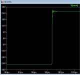
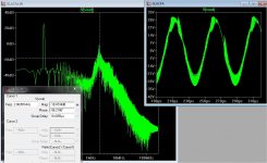
The limit ....
WAY out of the realm of any VFA ...
A damped ringing at 10pF (below 1) , UG at 5mhz - slewed 50v in .1us.
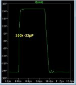
1/4 MHZ ! squarewave with ring (below 2) .. still stable.
33 or 47pF was more managable , UG at 2-3mhz. Much more stable than
any VFA at that freq.
Below 3 - perfect 100K SW -4R
The VSSA could beat this circuit in one category only - the no compensation
simulation.
Hawksford and CFA "get along" real well. 😎
I'm still amazed that an amp with a single compensation capacitor can
have .0005% THD20 ,almost 300v/us slew and a UG of 3mhz
and still work ! (It beats the tmc blameless easily).
OS
WAY out of the realm of any VFA ...
A damped ringing at 10pF (below 1) , UG at 5mhz - slewed 50v in .1us.
1/4 MHZ ! squarewave with ring (below 2) .. still stable.
33 or 47pF was more managable , UG at 2-3mhz. Much more stable than
any VFA at that freq.
Below 3 - perfect 100K SW -4R
The VSSA could beat this circuit in one category only - the no compensation
simulation.
Hawksford and CFA "get along" real well. 😎
I'm still amazed that an amp with a single compensation capacitor can
have .0005% THD20 ,almost 300v/us slew and a UG of 3mhz
and still work ! (It beats the tmc blameless easily).
OS
Attachments

So, we agree on this too.
About the VSSA, in order to deal with the base-emitter diode, i would had preferred an input cap than the big lytic at the emitter.
Then, try to change this cap by a BJT for DC coupling.
My proposal was this one:
http://www.diyaudio.com/forums/atta...cfa-topology-audio-amplifiers-nocap-vssa2.gif
To be improved, moving the input filter from input to the bases of the second transistors. It will add the resistance you promoted.
Something like this?
The 47pF is just an imaginary value.
Attachments
Guys, you really don't deserve a nobody like myself to continuously poop your party. Right or wrong has absolutely no relevance in front of this wave of enthusiasm.
If I only could identify what's behind this wave of enthusiasm and find out why, only a couple of years ago, CFA was a damned word here on this forum (and not only).
Merry that thing that I can't say (since I was already penalized for using an idiom that is considered offensive by people of certain religious backgrounds) and a Happy New Year.
And because I owe you an explanation for the year of 2013, here it goes:
As I am pretty sure there are not many people here understanding correctly what conditional or unconditional stability is, here's first the definition in layman terms. An amplifier with negative feedback having a closed loop gain CLG is called unconditionally stable if it is stable at each and every gain g<CLG. In terms of loop gain phase, this translates to the loop gain phase never reaching 180 degrees before the ULGF.
For a dominant pole compensated VFA, as many here noted, the gain*bandwidth=const. applies. To increase the loop gain beyond this, we need a higher order compensation method. Assuming a two pole compensation schema, obviously the phase dips before being brought back by the loop gain zero. The 2nd pole will double the rate at which the open-loop gain falls, that is, to 12 dB/octave or 40 dB/decade. If the open-loop gain has dropped below 0 dB (unity gain) before it hits the 2nd pole, the op amp will be unconditional stable at any gain. If the 2nd pole is reached while the loop gain is greater than 1 (0 dB), then the amplifier may not be stable under some conditions. The higher we push the ULGF up then it is unavoidable, at a certain point, to have the phase dip under 180 degrees. That's why a VFA is not always unconditionally stable, and chances to be so decrease as we increase the ULGF.
Now, think of true CFAs, where the relationship between gain and bandwidth above doesn't hold, true CFAs don't have a fixed gain-bandwidth product. The reality is that a true CFA gain does drop nowhere close to the regular 20dB/decade, like their VFA counterparts. This translates to eliminating the conditional stability in VFAs as above. If the gain doesn't drop by 20dB/decade, then the phase will also drop much slower (since we are considering only minimum phase systems, so phase and gain are not independent). Hence, it is possible to push the ULGF much higher and still have an unconditionally stable amplifier.
Now, is this anywhere important in audio? Certainly not much. First, because of the high closed loop gains, much of the CFA nice properties are lost, in fact any CFA that I've seen simulated in this thread behave 95% as a regular VFA. Secondly, the ULGFs at which this CFA property of unconditional stability becomes effective are usually much higher that anything that is practical in an audio discrete implementation, and in particular for power amplifiers.
Hope this clears the muddy waters.
Thanks for this Waly. This is indeed a clear and accurate statement of the issues. Not sure if it helps us though.As I am pretty sure there are not many people here understanding correctly what conditional or unconditional stability is, here's first the definition in layman terms. ....
... loadsa good pedantic stuff ...
......... Secondly, the ULGFs at which this CFA property of unconditional stability becomes effective are usually much higher that anything that is practical in an audio discrete implementation, and in particular for power amplifiers.
Hope this clears the muddy waters.
With some luck, the next stage will be when you post some practical circuits (or even SPICE world stuff) that helps us unwashed masses make use of this in the design of better amps without LTP i/ps which we may loosely call CFAs 🙂
A Merry X'mas to all.
Yes. (for the filter)Something like this?
Well, complexity is not a requisite, and you know damn well that what produce better numbers not always offer better sound...For what it's worth, it does not appear that it is any simpler than a corresponding VFA, so the CFA-is-simpler argument seems to go out the window 🙂.
We can add lot of stuff around, as long it is not in the signal path... (CCS and Cascoded VAS )... just as VFA...
After reading the last few posts .. doubts ??
Maybe I have a "controversial feedback amplifier" , oh well.
I'm "running" with it ... (new thread) bye 😉 .
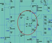
PS -The "cascoded VAS" with triple OPS sounds Sooooo nice - it's the CFA ? that is the unknown ...
Oh - bah humbug 😀


OS
Maybe I have a "controversial feedback amplifier" , oh well.
I'm "running" with it ... (new thread) bye 😉 .
PS -The "cascoded VAS" with triple OPS sounds Sooooo nice - it's the CFA ? that is the unknown ...
Oh - bah humbug 😀
OS
Last edited:
WAY out of the realm of any VFA ...
A damped ringing at 10pF (below 1) , UG at 5mhz - slewed 50v in .1us.
1/4 MHZ ! squarewave with ring (below 2) .. still stable.
33 or 47pF was more managable , UG at 2-3mhz. Much more stable than
any VFA at that freq.
Below 3 - perfect 100K SW -4R
The VSSA could beat this circuit in one category only - the no compensation
simulation.
Hawksford and CFA "get along" real well. 😎
I'm still amazed that an amp with a single compensation capacitor can
have .0005% THD20 ,almost 300v/us slew and a UG of 3mhz
and still work ! (It beats the tmc blameless easily).
OS
Those are good numbers, but with practical layout (inductive end C parasitics, board layout etc) you would probably have ringing etc. Nevertheless, a good demonstration of CFA performance capability.
For the PSRR issue, take a look here http://hifisonix.com/error-correction/
Those are good numbers, but with practical layout (inductive end C parasitics, board layout etc) you would probably have ringing etc. Nevertheless, a good demonstration of CFA performance capability.
For the PSRR issue, take a look here Augmented Feedback Error Correction (AFEC)
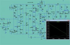
I have (some ) of the finer points of layout under control.
I'm really not after PPM entirely. I read your AFEC paper , the 2 OEM
triples I listen to use OP-amp servo's ... It would be awesome to
combine an AFEC/servo as I have a regulated +/-15v supply already.
But , for others to build .. KISS (keep it stupid simple 😀)
(below 1/2)... I am on line with a standard VFA in the PSRR department.
I tweaked the multiplier and used a "real" CCS.
Just 1 question ??? You use offset adjustment taken from the zener
regulators applied to NFB on the NX. It worked .... but OEM's mostly use "input side" offset compensation.
Why did you choose this method ?
PS- I separated the offset regulators from the diamond.
Of the 3 options (input , FB , or servo) which would be best ?
All else on my circuit is either acceptable or exceptional. 🙂
OS
Attachments
Have-you tried to apply feedback directly at the Q5,Q8 emitters ? (you can try by a double path)All else on my circuit is either acceptable or exceptional.
Have-you tried to apply feedback directly at the Q5,Q8 emitters ? (you can try by a double path)
Excellent , like the peeceebee/VSSA ? That might do it.
Will show the result next post.
OS
The meritorious decline in the delusionary malfeasance prone expletive dissertations to contend with too.
Oh, Don't take it so hard .....
-Richard
Last edited:
Yes. (for the filter)
Well, complexity is not a requisite, and you know damn well that what produce better numbers not always offer better sound...
We can add lot of stuff around, as long it is not in the signal path... (CCS and Cascoded VAS )... just as VFA...
Everything is in the signal path 🙂.
Cheers,
Bob
got it ..
Just one "stinking" cap ...
How I did it (below ).
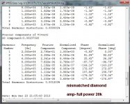
I did make THD go up ... OMG 😱 - from .0006 to .001x% (below 2) 🙄 .
Mismatched a zetex with a fairchild on the diamond - offset
is .2mv (better than the 992/1845).
Thinks I gotz it.. 🙂
PS - I pulled out my VSSA sim , added a couple diodes - used FB just like
the NX. Techniques are interchangable between both circuits.
Q5/Q8 are the dedicated level shifters/CF and the diamond is a very high impedance buffer .
NX is a "hybrid" , a VERY good one...(behaves like CF and VF) 😀.
OS
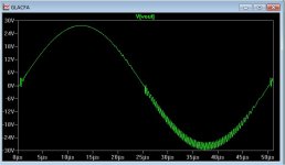
Just one "stinking" cap ...
How I did it (below ).
I did make THD go up ... OMG 😱 - from .0006 to .001x% (below 2) 🙄 .
Mismatched a zetex with a fairchild on the diamond - offset
is .2mv (better than the 992/1845).
Thinks I gotz it.. 🙂
PS - I pulled out my VSSA sim , added a couple diodes - used FB just like
the NX. Techniques are interchangable between both circuits.
Q5/Q8 are the dedicated level shifters/CF and the diamond is a very high impedance buffer .
NX is a "hybrid" , a VERY good one...(behaves like CF and VF) 😀.
OS
Attachments
Of course, dunno why i fear more serial killers than parallel ones 🙂Everything is in the signal path 🙂.
Happy Christmas to all of you. And a new year full of little steps in direction to perfect transparency.
Member
Joined 2009
Paid Member
What I have found in my simulations, CFA is simpler to compensate. I use OIC with CFA and getting very good PM and GM, but that was very hard to get working with VFA.
BR Damir
I found the same thing, compensation appears in simulations to be more robust. I assume this is because the feedback path doesn't have an active device in it - i.e. a singleton receives the input at the base and the feedback at the emitter, whereas in the LTP the input device receives the input at the base but the feedback at the emitter first gets buffered by the 'other' device in the LTP. The singleton has far less signal-dependent phase shift to deal with.
- Home
- Amplifiers
- Solid State
- CFA Topology Audio Amplifiers