Hi Andrew,
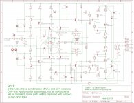
Here is another link to the schematic. As you can see, it is not just a standard VFA, rather a VFA with some 'current on demands' properties, that is, to a certain extent. This has been accomplished by means of a cross coupling resistor (and capacitor), see pic below.
Indeed, there are a lot of clamping diodes, which protect the TIS against deep saturation. But what has this to do with a 'huge OLG'? I think they are needed because the IPS is capable of delivering pretty large currents (according to Stochino <= 18mA).
Cheers, E.
The CoD adds only circa 15% more SR over and above the standard MC (250 V/us to the claimed 300 V/us).
Pretty pedestrian given the additional circuit complexity in my view and thus I classify it as a dominant pole compensated VFA.
Diamond input buffer or not --- if any circuit does not fundamentally look like this --- it is not a CFA. Strictly speaking. Everything seems to get simplified or dumbed down.... so now we have anything with feedback of any kind to an emitter/source as a CFA.
Just to stay clear. There is a difference. When we go to simplify this further..... down to a minimalist circuit, we could end up with something else. But that can also be pretty good with care.
Thx-RNMarsh
View attachment 387052
This is an attempt to have real CFA. Richard is this finally real CFA?
BR Damir
Attachments
By Bonsai -OS, the leach is a VFA.
With all due respect , I am fully aware of what the leach is (and isn't).
My simulation had the same even order cancellation and behaved electrically
similar to the the leach.
My point was that it performed far better with the same parts. Leading to
the fact that some other factor was involved (the method of FB).
I suppose I'll have to wait until Y'all decide on WHAT a CFA is before I take
a "whack" at it. I'm patient - go to it ...guys !
OS
Member
Joined 2009
Paid Member
It's VFA !
Output of amplifier feedback result is to produce a voltage signal at emitters of Q2 and Q5.
😀
What is relevant is that this is a complementary Singleton error amplifier. The I-V curve, phase shift etc. is different than dual LTP.
Output of amplifier feedback result is to produce a voltage signal at emitters of Q2 and Q5.
😀
What is relevant is that this is a complementary Singleton error amplifier. The I-V curve, phase shift etc. is different than dual LTP.
Last edited:
Bigun, i believe it is complicated enough for some readers to not introduce erroneous (humorist ?) inputs.
It IS a CFA. (Whatever we agree the name or not)
I wonder how, after more than one hundred pages on the subject, it is not clear in everybody's minds ?
It IS a CFA. (Whatever we agree the name or not)
I wonder how, after more than one hundred pages on the subject, it is not clear in everybody's minds ?
Last edited:
Member
Joined 2009
Paid Member
I'm quite serious, I think this thread has been a set-back in some regards. There are newbies in other threads asking if they should make a CFA or a VFA - without any understanding of what the heck this is all about. Rather than understand the topology there are people worrying 'do I have a CFA - please let me have a CFA, how do I know I have CFA, have I been in a cave the past 5 years, oh my gosh...' 😀
Last edited:
Bigun, i believe it is complicated enough for some readers to not introduce erroneous (humorist ?) inputs.
It IS a CFA. (Whatever we agree the name or not)
I wonder how, after more than one hundred pages on the subject, it is not clear in everybody's minds ?
IF someone posted two examples of each, CFA and VFA with diagrams and explanations, it would not be enough.
So until something is agreed upon and BUILT, to who's spec I do not know, the debate goes on. I am sure OS Alex or even I could layout out a PCB and NO ONE will build it.😛
Member
Joined 2009
Paid Member
An example of both 'types' of feedback - in one amplifier - on one pcb.
It can be built with dual LTP at the front end, or with dual singleton at the front end.
In the case of the LTP input, there is a single feedback loop of high impedance to the bases of the LTP feedback devices.
In the case of the singleton input, there are two feedback loops of low impedance to the emitters of the singleton devices.
Pretty much everything else remains unchanged.
Attachments
An example of both 'types' of feedback - in one amplifier - on one pcb.
It can be built with dual LTP at the front end, or with dual singleton at the front end.
In the case of the LTP input, there is a single feedback loop of high impedance to the bases of the LTP feedback devices.
In the case of the singleton input, there are two feedback loops of low impedance to the emitters of the singleton devices.
Pretty much everything else remains unchanged.
Throw in a Cap Multi on the front end and make a OS style separate OPS for Mosfet or BJT and Lets LOCK and LOAD, with output at least 100W.😱
I'm quite serious, I think this thread has been a set-back in some regards. There are newbies in other threads asking if they should make a CFA or a VFA - without any understanding of what the heck this is all about. Rather than understand the topology there are people worrying 'do I have a CFA - please let me have a CFA, how do I know I have CFA, have I been in a cave the past 5 years, oh my gosh...' 😀
.... I am sure OS Alex or even I could layout out a PCB and NO ONE will build it.😛
Favourite posts of 2013
Member
Joined 2009
Paid Member
Hi Krisfr,
This is a unique design, you can't put a cap multi or any kind of RC filter on the power rails to the front end. If built in CFA mode it will need a clean power supply, simple as that.
I'm not proposing this design for you fella's - I bow before OS when it comes to design and build of amplifiers. My TGM7 project is just for my own enjoyment - assuming it works!
Then let there be a short term consensus, and let OS be agreeable to build it and then have a face off comparison with the VFA protagonist putting forth a cutting (bleeding) edge SOA challenger.
THEN maybe some listening can determine what everyone thought in the beginning is still true.
The CFA-VFA battle of DIYAudio Channel.
Terminator T1 vs T4 or T5 newest versions allowed, or Chocolate vs Strawberry with or with nuts. Nobody like vanilla.
THEN maybe some listening can determine what everyone thought in the beginning is still true.
The CFA-VFA battle of DIYAudio Channel.
Terminator T1 vs T4 or T5 newest versions allowed, or Chocolate vs Strawberry with or with nuts. Nobody like vanilla.
I do believe Bonsais description is the best and clearest off all. In spice its quite easy to look at a circuit to see what it reacts on. try to place a current at the backside of an LPT and see what the does to the signal through the amp..?? NO change the Feedback injection node responds to voltage. the try to add a voltage to the feedback injection point of a CFA, then the amp will stop producing useable output, but inject a current there instead and see how that is scaled at the output.(alters voltage). CFA reacts to current, VFA react to voltage modulation at the feedback injection point.
Member
Joined 2009
Paid Member
Remember, a transistor is a voltage controlled device (bipolar, FET or tube). You can push or pull a current through the emitter/source/cathode but ultimately it creates a voltage at that point. This voltage is what the emitter responds to. Of course, the emitter/source/cathode is a low input impedance control point, it needs current or you won't be able to hold a voltage at that point. All error amplifiers react to a voltage modulation.
What is more important is the topology and operating points - worrying about whether it is a CFA or a VFA, or one definition for it is clearer than another adds no value, in my view, to an understanding of the amplifier. It might be of comfort if you've hitched your wagons to one or the other though.
Some circuits can be poorly designed if not approached carefully. Thinking of bipolar devices as current controlled can result in designs that rely on the transistor current gain for their operating points - which isn't ideal.
I believe you are better off thinking of a feedback loop that ultimately presents a differential voltage - which means there is not just the traditional feedback path, there must also be a reference voltage - signal ground or a supply rail. The quality of the feedback signal depends on both.
Last edited:
Looking at some poster's crusades since the beginning of this thread, i believe the people you refer to are suicidal. 🙂without any understanding of what the heck this is all about. Rather than understand the topology there are people worrying 'do I have a CFA - please let me have a CFA,
Back to the beginning...

Member
Joined 2009
Paid Member
Hopefully not suicidal ! 😱
Back to basics, reminds me of Nelson's approach. He has remarked that one of his favourite tricks is to think of a circuit in terms of the voltages, and also think of it in terms of the current. He doesn't, as far as I know, treat one circuit as voltage and another circuit as current but applies both to the same circuit. It is a way of looking at the same things from different perspectives not a process to categorize things. And he credits one if his most important inventions, the Aleph current source, with this flexibility in how he views circuits. A current mirror can thus also be analysed in voltage terms.
Anyhow, I am most curious about the 'VFA vs CFA' in my TGM7, I hope it works so I can find out if I can hear any difference.
Last edited:
Bigun, why don't you stop to consider the 'current' in the CFA name as a description of the topology ?
Call-it "Joe", if you prefer... and eat at Joe ;-)
Call-it "Joe", if you prefer... and eat at Joe ;-)
Dadod -- Yes, it is real CFA.
Add your CCS, cascoding, improved mirror/conveyors and I/O buffers to taste.
If you add some R's to eliminate early voltage you get this:
View attachment CFA perhaps..pdf
Beginning to look familiar?
My design of the late 70's which was published in 1980. It has slowly become the new audio design standard since then.
I got a phone call while working at LLNL from Comlinear design engineer when my circuit was published in TAA. he asked a lot of questions on why I did this and that etc because he was working on similar design. later, in 1982 the patent came out on the CFA and in 1989 the first monolithic CFA was produced (EL2020). The addition of the current-mirror and the diamond buffer on the I/O was the CFA shown. BTW - R.Baker from MIT described his 'diamond' buffer in an IEEE paper in 1963.
If you look at the diamond buffer and reverse all the e-c's you get the amp I described in 1980.... maybe call it a diamond amp topology.
My question to everyone is this -- is it also a CFA? 🙂
Thx-RNMarsh
Last edited:
Last edited:
- Home
- Amplifiers
- Solid State
- CFA Topology Audio Amplifiers