Waly you are applying tools that describe the output quantity being measured (voltage or current) to the inner workings of an amplifier topology and its the wrong tool IMV.
Both CFA and VFA toplogy amplifiers generate an output voltage that is related to the gain and the input voltage - i.e. output voltage is the controlled variable. Thats what we are sampling and feeding back to the error amp.
Both can also be configred such that current is the controlled variable.
But, in a CFA, the feedback from the controlled output quantity in in the form of a current, and in a VFA, in the form of a voltage.
If you apply the tool you propose, you always end up as I noted earlier with the same answer i.e. CFA=VFA which is correct if you are talking about the output controlled quantity but wrong about the way the feedback is delivered to the error amplifer stage.
ok?
Last edited:
Speaking of Budgets, @ a dollar a page, this is some costly reading, maybe Santa can find one of these in the coal bin.
This is dirt cheap reading compared to what education costs today. Anyway, there are also libraries and other methods to get books for less, or even for free.
I got that book (in soft cover, 1995) from a bookshop, underneath Waterloo Bridge on Queen's Walk, for 20% the list price. The Amazon link was only a convenient reference.
Good night.
No. I don't understand why one would need to use a special tool or view, when the general canonic approach is delivering the right results and completely characterizes the so-called CFAs. I am not saying CFA=VFA, but that the CFA properties can be determined using the canonic analysis tools. Having as a plus the advantage to demystify some of the "magic" CFA properties, like CFAs are delivering more loop gain for the same phase margin, etc...
Good night.
No magic about CFA, just solid engineering. And they certainly don't deliver more loop gain for the same phase margin.
Member
Joined 2009
Paid Member
But, in a CFA, the feedback from the controlled output quantity in in the form of a current, and in a VFA, in the form of a voltage.
This is not quite accurate. Since the error amplifier is a voltage controlled device the feedback loop MUST eventually present the 'controlled output quantity' in the form of a voltage and in order to deliver this voltage it must also deliver enough current to satisfy the input impedance of the error amplifier. But it is still a voltage that the error amplifier responds to in a properly designed circuit. It matters not whether the impedance for the feedback signal as seen by the output stage is low, or high.
Some folk like to call low impedance loops as being dominated by 'current' and high impedance by 'voltage' and hence the popular use of the terms CFA & VFA - an unfortunate thing perhaps. It's an oversimplification that serves a purpose but loses usefulness when discussions get into detailed understanding.
The more important aspect is the topology and I think there is more to be gained by seeking an understanding of the performance of the topologies without trying to fix imprecise labels like VFA or CFA to them.
Last edited:
Member
Joined 2009
Paid Member
This approach is still trying to use imprecise labels to divide varied topologies into two categories. Of course it become convenient to affix labels, then to affix a way of approaching the design and analysis. But when we also try to claim one is better than the other we create confusion and argument. It's no different in politics - polarization around concepts that are used to divide people into two camps - which doesn't help. The history of this thread surely shows that there is a fundamental problem with the idea that amplifiers can be divided between these two camps and that one is better than the other.
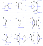
My suggestion was to focus on the topology without calling it VFA or CFA. Compare the LTP with the Singleton, for example (and their symmetric counterparts). Is an LTP a Singleton where the feedback loop has been buffered with an emitter follower ?
OK so figure 1 is a CFA and figure 7 is a VFA 😀
It's a bit clearer with these two figures, how you add an EF buffer to figure 1 and you get yourself a Rush cascode like figure 7. In both cases you could design a low impedance feedback loop. You can not use a high impedance feedback loop with figure 1 because the input impedance of the emitter is too low.
The emitter of the error amplifier in either figure 1 or 7 doesn't 'know' if there's a low impedance feedback loop or a high impedance loop with an EF buffer. But the EF buffer will introduce additional phase delay and non-linearity. And as Bonsai points out, the EF buffer will not deliver higher current with higher signal levels whereas a low impedance feedback loop can.
Last edited:
Think about the Wurcer test . . .
Keep (canonical) feedback topology separate from amplifier topology - it makes it easier to understand IMV.
But, you are right, there's too much discussion on this point - the main focus should be on building better amplifiers.
Keep (canonical) feedback topology separate from amplifier topology - it makes it easier to understand IMV.
But, you are right, there's too much discussion on this point - the main focus should be on building better amplifiers.
Last edited:
This claim of Waly's is the only useful pearl of wisdom recently ... IF it is true.The "current on demand" property (responsible for the very high slew rate) is not specific to a "CFA". It can be implemented in a VFA as well.
The rest of his stuff comes under the interminable semantic pedantic BS that he seems to delight in starting & provoking ... but which is of no use to man or beast.
As he's reluctant to enlighten us unwashed masses, does anyone else know what he is talking about and can show us a circuit? Or is it the usual unicorn?
Last edited:
Different "personalities"
I've never simulated a CFA before.
It "feels" like a leach amp on steroids 😱 (simulation wise).
The Nakamichi diamond amp (620) is the only VFA that can
be as fast.
The 2 amps I just simulated have another "phenomenon" going on.
They Don't behave like VFA's ... at all.
OLG plot is totally different from a VFA.
Same dual 47pf compensated VAS as the leach
but 3 times the slew. maybe they are not VFA's.
Just some observations ....
OS
That's just the kind of title OS would give an amplifier 😀
Good idea .... you thought of it 😀 . It would be built just because of the "catchy" name...
The Controversy is trivial , someone should build a damn amp. I'm out of toner ,
but I'll make the board (with a perfect layout - no smoke/hum).
OS
I've never simulated a CFA before.
It "feels" like a leach amp on steroids 😱 (simulation wise).
The Nakamichi diamond amp (620) is the only VFA that can
be as fast.
The 2 amps I just simulated have another "phenomenon" going on.
They Don't behave like VFA's ... at all.
OLG plot is totally different from a VFA.
Same dual 47pf compensated VAS as the leach
but 3 times the slew. maybe they are not VFA's.
Just some observations ....
OS
OS, the leach is a VFA.
The 2 tests:-
1. The LTP's are fed from current sources so the peak current into the TIS is limited to the LTP current. In a CFA, the peak current is determined by the feedback resistor value.
2. If you plot the closed loop response and change the gain (say from 20 dB to 50 dB) you will see the - 3dB bandwidth reduce as the gain increases (I assume you are looking at the leach with MC here). This is a MC comp'd VFA obeying the constant gain bandwidth constraint caused by dominant pole compensation.
2 of the three pointers for VFA are met
1. Both the inv and non-inv inputs are high impedance ~ voltage feedback
2. 2 gain stages (LTP and VAS)
(3rd pointer: in classic CFA, the gain stage is in the form of a transadmittance amplifier - i.e. current mirror. but, CFA with TIS is also possible)
IIRC correctly, the Leach uses a 22 pF Cdom and the LTP current is quite high, so its pretty fast for a legacy VFA - just shows how far ahead of the game ML was. RIP)
Last edited:
This claim of Waly's is the only useful pearl of wisdom recently ... IF it is true.
...
As he's reluctant... does anyone else know...and can show us a circuit?
I wouldn't claim to know what he means, but pretty close are the series of amps by Stochino in Electronics World (AKA Wireless World) October 1995, April 1997, August 1998. There was also one in March 1996 that I don't have handy.
Do you know these or were they about the time you were out of the scene?
VFA with 300v/usec, not that it matters, but the discussion is educational.
Best wishes
David
Last edited:
do you have links Dave?
I don't think it is public domain yet, Electronics World still has ownership AFAIK.
I only have old, actual paid-for paper copies or photocopies.
Of course you could search a bit 😉
Best wishes
David
Last edited:
This was the period when I was already planning my departure from the civilised world. I vaguely remember Stochino but not anything useful from him.I wouldn't claim to know what he means, but pretty close are the series of amps by Stochino in Electronics World (AKA Wireless World) October 1995, April 1997, August 1998. There was also one in 1996 that I don't have handy.
Do you know these or were they about the time you were out of the scene?
VFA with 300v/usec, not that it matters, but the discussion is educational.
Waly implies (via Huijsing et al) that this VFA with zillion V/us slew is applicable to Low Power OPAs. I would certainly find this more interesting than my Jurassic recollections of Stochino.
Self http://www.douglas-self.com/ampins/library/ampartew.htm#90 flags two of his articles as First Rate / Innovative 😱 but his name is coloured blue which might be Misleading or pointless
Anyone have copies of the important Ultra Super Fast Amp articles?
Or more interestingly, pics from Eschauzier & Huijsing?
Last edited:
Waly implies (via Huijsing et al) that this VFA with zillion V/us slew is applicable to Low Power OPAs. I would certainly find this more interesting than my Jurassic recollections of Stochino.
I assume his point is that the techniques needed to produce an acceptable slew rate in a micro-power amp or with a 1 volt power supply can equally produce an enormous slew rate in a conventional amp.
The later Stochino articles were audio amp oriented but the circuit concepts were drawn from op-amp examples.
Best wishes
David
Last edited:
Amazing -
It has happened before in history where one lone person was correct all along. In the case of CFA you are up against, the designers/inventors at Comlinear, TI, AD, LT etc etc as well as academics and researchers and many published works on the subject... technical papers and books. Personally, I don't see this leaves one with much room for a new Interpretation. Let's go with the flow for awhile and see what happens.
Thx-RNMarsh
Really
I've already posted in this thread all the underlying math to justify my interpretation, those interested can search for and draw their own conclusions.

It has happened before in history where one lone person was correct all along. In the case of CFA you are up against, the designers/inventors at Comlinear, TI, AD, LT etc etc as well as academics and researchers and many published works on the subject... technical papers and books. Personally, I don't see this leaves one with much room for a new Interpretation. Let's go with the flow for awhile and see what happens.
Thx-RNMarsh
Last edited:
Self... two of his articles as First Rate / Innovative 😱 but his name is coloured blue ...
This is a colour typo. Self quotes him respectfully in the book.
Best wishes
David
- Home
- Amplifiers
- Solid State
- CFA Topology Audio Amplifiers