Most of them are added (predicted or measured) modulating error to the output(like wavebourn did, also that jfet), and adding measured error back to the input(like bob Cordell did).
OK That's it? That all? Surely there are more means and methods. Which topologies are best for cancellation means?
Thx-RNMarsh
Last edited:
Marcel, do you speak about Peter Blomley?
No, the Blomley configuration (New approach to class B amplifier design, Wireless World February and March 1971) is quite different from a circuit with class-AB control loop. Blomley basically has a stage that splits the current into two parts and then two special high-gain current mirrors as the output stages. The stage that does the splitting is part of the normal signal path.
The class-AB control loops I talk about are more or less orthogonal to the signal path. You have a signal feedback loop controlling the difference between the currents through the output devices. A separate loop that always increases or decreases both currents at the same time controls some non-linear function of the currents through the output devices. That non-linear function is usually chosen such that near the amplifier's quiescent bias point its value mainly depends on the sum of the currents through the output devices, and for large output currents its value depends mainly on the smaller of the two output device currents.
The earliest reference to a class-AB control loop I know of is Johan H. Huijsing and Frans Tol, "Monolithic operational amplifier design with improved HF behavior", IEEE Journal of Solid-State Circuits, April 1976. They used a product rule loop, that is, the extra control loop controlled the product of the two output device currents. Later implementations often use an harmonic mean rule. For almost discrete amplifiers, exp(-R*I1)+exp(-R*I2) is easier to make.
For distortion figure, tuned version (like halcro did) will give best result, but the sound is getting feels like deeper. While added anti error signal to the output (modulated) needs careful selection of devices and topology used (mostly work fine in classA).OK That's it? That all? Surely there are more means and methods. Which topologies are best for cancellation means?
Thx-RNMarsh
Are we all done with CFA topology? Everyone got it? What it is and how it works best and pro-con. Myths?
All done?
Thx-RNMarsh
All done?
Thx-RNMarsh
Are we all done with CFA topology? Everyone got it? What it is and how it works best and pro-con. Myths?
All done?
Thx-RNMarsh
Not quite. Seems JB from tubecad.com thinks single ended CFA's exist as well. Theres hope for my singleton yet! 😉
Not quite. Seems JB from tubecad.com thinks single ended CFA's exist as well. Theres hope for my singleton yet! 😉
Got proof? or at least an entertaining story?
-RNM
keep Harold Black's 2 schemes, principles separate
" and adding measured error back to the input"
Cordell/Hawksford "Error Correction" is negative feedback - despite some cute drawings it operates entirely as negative feedback around a positive feedback gain boosting inner loop
has been known to be negative feedback for decades before Hawksford, all it takes is really working through the arithmetic
Horowitz 1963 textbook is clear on "alternative" linear feedback topologies equivalence - Cordell/Hawksford Error Correction is even the simpler "1 degree of freedom" negative feedback
Horowitz' 2nd degree of freedom in negative feedback loops is signal feedforward into the single output amp stage, either explicit injection of a signal or "coding" the knowledge into a pre filter
and this is from [ref 24] cited above
for situations where we have knowledge of device nonlinearity it is possible to predistort for cancellation - limited by the matching of the model and the real device distortions
Horrowitz' 2nd degree of freedom feedforward injection is a way to view adding the “pre distoriton” signal in a single power output amplifier
by measuring the error and feeding to a 2nd power amp we get the other side of Hawksford's drawing: Black's 1st feedforward correction scheme - the difference is that it requires 2 power amps, and a way to combine their outputs such that they behave independently - not just paralleling or averaging
Most of them are added (predicted or measured) modulating error to the output(like wavebourn did, also that jfet), and adding measured error back to the input(like bob Cordell did).
" and adding measured error back to the input"
Cordell/Hawksford "Error Correction" is negative feedback - despite some cute drawings it operates entirely as negative feedback around a positive feedback gain boosting inner loop
has been known to be negative feedback for decades before Hawksford, all it takes is really working through the arithmetic
Horowitz 1963 textbook is clear on "alternative" linear feedback topologies equivalence - Cordell/Hawksford Error Correction is even the simpler "1 degree of freedom" negative feedback
Horowitz' 2nd degree of freedom in negative feedback loops is signal feedforward into the single output amp stage, either explicit injection of a signal or "coding" the knowledge into a pre filter
my mistake, shouldn't have added the comma
http://www.control.lth.se/~kja/modeluncertainty.pdf
From K J Astrom “Model Uncertainty and Robust Control”
“fair use” excerpt:
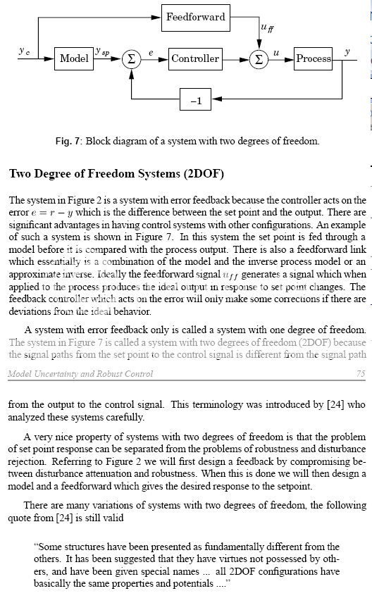
Be sure to read that last para!
and this is from [ref 24] cited above
The counterargument:
Hawksford/Cordell error correction is a 2 degree of freedom linear feedback control system,
All expressions of 2 degree of freedom control systems are equivalent.
Therefore Hawksford/Cordell error correction is equivalent to conventional error feedback with a command prefilter
Therefore the output linearizing disturbance rejection effect is exactly equivalent to error feedback and has the same gain-bandwidth/stability limits of ordinary 1 degree of freedom error feedback
A little reading: (slow to load, ~ 500K )
[I've referenced this a few time before in this thread I.M. Horowitz, "Synthesis of Feedback Systems" 1963 - that mkes this a 40+ year old "controversy"]
I like Bob's circuit, I do think understanding it as a local feedback loop and tailoring its loop gain and frequency response is likely to be a good way forward
for situations where we have knowledge of device nonlinearity it is possible to predistort for cancellation - limited by the matching of the model and the real device distortions
Horrowitz' 2nd degree of freedom feedforward injection is a way to view adding the “pre distoriton” signal in a single power output amplifier
by measuring the error and feeding to a 2nd power amp we get the other side of Hawksford's drawing: Black's 1st feedforward correction scheme - the difference is that it requires 2 power amps, and a way to combine their outputs such that they behave independently - not just paralleling or averaging
I have posted working sims showing Quad's and a "parallel Black's Feedforward version from the Vanderkooy and Lipshitz paper
this web site has publication references Libero - Community - I siti personali
Marcel, do you speak about Peter Blomley?
Maybe I misunderstood the question, and the answer should be: yes, Peter Blomley is among those who don't like their output stages to switch off.
Thank you for your inputs, I realize that my question was not accurate. Yes, this may be the answer as well. I have also made some experiments with output stages based on ideas of Ian Hegglun D2S, but at low power like 2 x 50W only. Interesting, but I have not accepted the idea for a serious project.
I have also made some experiments with output stages based on ideas of Ian Hegglun D2S, but at low power like 2 x 50W only. Interesting, but I have not accepted the idea for a serious project.
Pavel, why is that? Were you not satisfied with the results?
Jan
...
Hawksford/Cordell error correction is a 2 degree of freedom linear feedback control system,
All expressions of 2 degree of freedom control systems are equivalent.
Therefore Hawksford/Cordell error correction is equivalent to conventional error feedback with a command prefilter
...
Horowitz 1963 textbook is clear on "alternative" linear feedback topologies equivalence - Cordell/Hawksford Error Correction is even the simpler "1 degree of freedom" negative feedback
Have you altered your view or is the last sentence suspect?
Best wishes
David
Pavel, why is that? Were you not satisfied with the results?
Jan
Jan, my attempt was not universal enough. When I tuned it for 8 ohm load, with low distortion and amplitudes of individual harmonics had fast decay, it did not work for 4 ohm load and distortion profile resembled cross-over distortion profile then.
picky, pickyHave you altered your view or is the last sentence suspect?
I last remember thinking the Cordell/HEC is a single degree of freedom loop - everything can be resolved into a simple error feedback loop
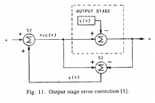
from Bob's "MOSFETPowerAmplifier with Error Correction" article:
Attachments
picky, picky
I last remember thinking the Cordell/HEC is a single degree of freedom loop - everything can be resolved into a simple error feedback loop
from Bob's "MOSFETPowerAmplifier with Error Correction" article:
Yes, the HEC arrangement can be viewed as a local negative feedback loop where the combination of summers can be reconfigured to show a unity-gain positive feedback loop in the forward path. Thus, in principle, when things are properly adjusted, there is infinite loop gain. As with any other feedback loop, this infinite loop gain must/will be brought down as frequency increases. The topology itself does have practical advantages, as described in my book. Indeed, HEC requires local compensation. However, interestingly, the primary compensation in the loop acts as a feedforward to the signal, not killing the signal bandwidth. The HEC circuit also forms a very tight local loop, and with fast MOSFETs works quite well.
As I have said before, the different ways of looking at HEC provide different useful insights.
Cheers,
Bob
Not quite. Seems JB from tubecad.com thinks single ended CFA's exist as well. Theres hope for my singleton yet! 😉
Offcource they do, in fact theres more topologies than just the known singleton topology shown on this forum. 😉
Got proof? or at least an entertaining story?
-RNM
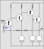
Well given John Broskie's style probably more the latter. Here's a link to the article and basic schematic. I may attempt Mr Wurcer's tests but i scared him off with my last interpretation!
Page Title
Attachments
" and adding measured error back to the input"
Cordell/Hawksford "Error Correction" is negative feedback - despite some cute drawings it operates entirely as negative feedback around a positive feedback gain boosting inner loop
has been known to be negative feedback for decades before Hawksford, all it takes is really working through the arithmetic
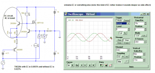
Yes, this kind EC is working on negative feedback loop, even for simplest form, I don't now what is this EC name, you could call it ontoaba EC or something else😉. 0.0055%THD 20k in sim working on simple common feedback.
Attachments
Last edited:
Well given John Broskie's style probably more the latter. Here's a link to the article and basic schematic. I may attempt Mr Wurcer's tests but i scared him off with my last interpretation!
Page Title
Replace all those CCS with complimentary transistors and you are right back here.
THx-RNMarsh
- Home
- Amplifiers
- Solid State
- CFA Topology Audio Amplifiers