Member
Joined 2009
Paid Member
I have noticed, in simulations of a CFB version of my TGM7 amplifier something interesting and either wrong or if it's correct then it's troubling - about symmetry. The nfb is great at compensating for lack of symmetry between devices. But it can't compensate for anything that is outside of the gnf loop. The feedback loop itself is subject to asymmetry. Try changing the value of the feedback loop shunt resistor in one side only. I needed only 0.5% imbalance to significantly increase distortion. You need accurately matched resistors and equal length pcb traces to avoid this. And if you have capacitors in your feedback shunt network - good luck matching those. I did not find such sensitivity with the VFA version.
I have noticed, in simulations of a CFB version of my TGM7 amplifier something interesting and either wrong or if it's correct then it's troubling - about symmetry. The nfb is great at compensating for lack of symmetry between devices. But it can't compensate for anything that is outside of the gnf loop. The feedback loop itself is subject to asymmetry. Try changing the value of the feedback loop shunt resistor in one side only. I needed only 0.5% imbalance to significantly increase distortion. You need accurately matched resistors and equal length pcb traces to avoid this. And if you have capacitors in your feedback shunt network - good luck matching those. I did not find such sensitivity with the VFA version.
Already pointed in many threads , imbalance can be reduced
by connecting a capacitor between the two loops terminals,
capacity has to be high enough for efficency at lower frequencies
but all in all yet another drawaback of dual loop in thoses so called CFAs...
What character? I don't want my amps with any character, I want them neutral.
Neutral is one of the characters. Anyway, most 0.000x%THD amps are not neutral nor natural.
@Richard,, is this one example?
JFET Follower Amplifier Cancels Distortion | Analog content from Electronic Design
Yes, that is a good example. 🙂 See what he used to do it with?
THx-RNMarsh
Last edited:
any analysis showing how it works?
for one, at audio frequencies junction C modulation isn't exactly the biggest distortion source, way behind gm, beta modulations, for BJT the forward bised junction C is much larger than reverse
reverse biased PN junction capacitance is a inverse sqrt function of reverse bais V with doping concentraion and grading profile determining the constants
for different polarity Q, particularly discrete the constants in the equation are going to be different, unknown to most users
the series expansion will have both even and odd terms - are you somehow matching the 2nd order term with your proposed distortion trim cap? - where in the circuit do they even go to have a highly linear added C change the nonlinear terms?
All great questions... as indicated- there isn't much published about the approach so we have an opportunity to make some new audio circuits here.
First let me put up again some real world data -- again, measured and not SIM. These are CFA power amps that I designed and had built several years ago - just as our economy went over the cliff to never return.
The THD was done at that time with an A-P SYS One which really could not accurately read what the amps could do-- just measuring itself plus a little added noise. But here it is from a decade plus back in time.


Thx-RNMarsh
Member
Joined 2009
Paid Member
Already pointed in many threads , imbalance can be reduced
by connecting a capacitor between the two loops terminals,
Thank you - no idea how I missed that one - especially as I used such a method on TGM5. But this is key for my CFA TGM7 - you saved me from a 'Duh' moment !
All great questions... as indicated- there isn't much published about the approach so we have an opportunity to make some new audio circuits here.
First let me put up again some real world data -- again, measured and not SIM. These are CFA power amps that I designed and had built several years ago - just as our economy went over the cliff to never return.
The THD was done at that time with an A-P SYS One which really could not accurately read what the amps could do-- just measuring itself plus a little added noise. But here it is from a decade plus back in time.
View attachment 384206
View attachment 384208
Thx-RNMarsh
Hi Richard,
What's the fundamental frequency?
Cheers,
Bob
CFA + Cancellation = ?
Greetings, Bob -- I only have this proto-type measurement here.... production was better... note it is a worse case -- only 1dB below clipping at 250W. Unmeasureable (at that time) at lower levels of power output. Which is basically why the test was done at such high power output near clipping... to get some numbers. Two channels both driven simultaneously... only channel shown.
I expect we could do a lot better today.

THX-RNMarsh
Hi Richard,
What's the fundamental frequency?
Cheers,
Bob
Greetings, Bob -- I only have this proto-type measurement here.... production was better... note it is a worse case -- only 1dB below clipping at 250W. Unmeasureable (at that time) at lower levels of power output. Which is basically why the test was done at such high power output near clipping... to get some numbers. Two channels both driven simultaneously... only channel shown.
I expect we could do a lot better today.
THX-RNMarsh
Last edited:
Is your VFA version also a 'symmetrical' topology?Try changing the value of the feedback loop shunt resistor in one side only. I needed only 0.5% imbalance to significantly increase distortion. You need accurately matched resistors and equal length pcb traces to avoid this. And if you have capacitors in your feedback shunt network - good luck matching those. I did not find such sensitivity with the VFA version.
Does it have 2 parallel feedback paths?
Can you name a few? What do you hear with them that isn't neutral or natural?ontoaba said:Anyway, most 0.000x%THD amps are not neutral nor natural.
Last edited:
Now, nobody can pretend any more here CFAs are not able to achieve VFA's low distortion levels.There you go, you`ve got your MAGIC number. What now?😉
Now, we have to put Dadod under arrest as a serial myth killer.
It would be the same with dual loop in "so called" VFAs. Dual loop is not a requisite in CFAs. Just an easy way to achieve input DC coupling with minimal component numbers.but all in all yet another drawaback of dual loop in thoses so called CFAs...
Already pointed in many threads , imbalance can be reduced
by connecting a capacitor between the two loops terminals,
capacity has to be high enough for efficency at lower frequencies
but all in all yet another drawaback of dual loop in thoses so called CFAs...
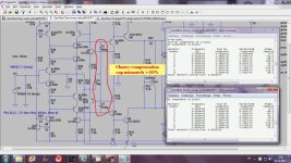
This is good exsample. Cherry compensation, C6 -10% and C9 +10%, THD20k at 100W/8 increased from 0.000137% with perfectly matched caps to 0.000153%. Insignificant!
Damir
Attachments
This is good exsample. Cherry compensation, C6 -10% and C9 +10%, THD20k at 100W/8 increased from 0.000137% with perfectly matched caps to 0.000153%. Insignificant!
Damir
There you go !
😎🙂
What does this means ?Neutral is one of the characters. Anyway, most 0.000x%THD amps are not neutral nor natural.
If an amp produce no distortion, it is neutral, by definition.
If you find an amp not neutral, with real loads, this means it produce distortions, not measured with resistive loads and sinus waves.
This means we have to find other ways to measure distortions.
This is good exsample. Cherry compensation, C6 -10% and C9 +10%, THD20k at 100W/8 increased from 0.000137% with perfectly matched caps to 0.000153%. Insignificant!
Damir
Hi dadod, have you practically built that amplifier? I'm thinking of designing a PCB for it and then to try to build it, would it obtain those perfect results in practice? Is it a stable enough amplifier or it needs some extra compensation?
Thank you!
Hi dadod, have you practically built that amplifier? I'm thinking of designing a PCB for it and then to try to build it, would it obtain those perfect results in practice? Is it a stable enough amplifier or it needs some extra compensation?
Thank you!
This is just simulation. I think it needs some more polishing, it shows strange oscilation on positive side of square wave simulation, I just didn't have time to investigate more. From the Bode plot it looks very stable, but that square test warred me.
Nothing's happening here.
THD1k is 0.000000% !!!
Damir
And this is with vertical MOSFET OPS. THD1k at 50W/8 ohm is 0.000000%.
It uses Cherry compensation with shunt compensation and 120 dB of NFB at 1 kHz.
Damir
What was the ULGF in both cases?
What was the ULGF in both cases?
Here are the square wave plots and Loop Gain plots for both amps, MOSFET and triple BJT.
I hope it's clear from the plots what was the ULGF.
Damir
Attachments
-
 GainWire-Cherry-comp.verticalMOSFET-OPS-square.gif200.4 KB · Views: 263
 -
 GainWire-Cherry-comp.tripleOPS-square.gif206.8 KB · Views: 265
 -
 GainWire-Cherry-comp.verticalMOSFET-OPS-Cherry outside Tian-LG.gif219.6 KB · Views: 261
 -
 GainWire-Cherry-comp.verticalMOSFET-OPS-Cherry intside Tian-LG.gif221.4 KB · Views: 238
 -
 GainWire-Cherry-comp.tripleOPS-Cherry inside Tian-LG.gif225 KB · Views: 164
 -
 GainWire-Cherry-comp.tripleOPS-Cherry outside Tian-LG.gif225.8 KB · Views: 164
I would sure like to know how that amplifier is supposed to have the almost no existent distortion numbers and could have anything like those square wave plots. Something doesn't compute here.
I would sure like to know how that amplifier is supposed to have the almost no existent distortion numbers and could have anything like those square wave plots. Something doesn't compute here.
Oh, it does compute, I use computer you know.😀
Thank you for the clues. Matching the C's seems to be important and does make sense to me.
Is it a case of making sure everything is completely symmetrical or at least as close as possible? I understand you can never get completely complementary NPN / PNP pairs but you can try to mitigate the differences.
I will search out your headphone amp and study it.
Symmetrical topology is used for easier cancellation methods.
If you do a lot of SIM, try to get the -120dB numbers from SIM and if not, then see what you have to do to that SIM which will get you those real world numbers.
Thx-RNMarsh
- Home
- Amplifiers
- Solid State
- CFA Topology Audio Amplifiers