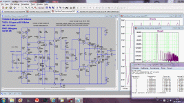
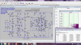
The scripting on the schematic is, in a classic sense, correct. One loop samples the output voltage, the other the output current. In the spirit of this thread, you may though call the "voltage feedback" as "current feedback", since it is fed into a low impedance node. YMMV.
Hi Waly !
This type of combined VFB & CFB loops but with manual adjusting of mutual FB levels first time I have observed applied in Electro Voice A series of tube power amps schematics produced from somewhere of mid 50` ,
where E.V. amp designer main intention was to achieve so called critical damping of loudspeaker unit for best bass & overall sonic performance .
Best Regards !
+1It would be nice to have a small section on 'simple' CFA inputs rather than promote only the evil diamond input CFA.
I think that the transistors which the feedback network is connected to have less distorsion when fed by a low impedance source. Without diamond input, it would preferable to have a buffer before the input of the amp, then the whole circuit becomes more complex. The followers of the diamond circuit are a very good feature.Originally Posted by kgrleeIt would be nice to have a small section on 'simple' CFA inputs rather than promote only the evil diamond input CFA.
if you look at symmetrical from another view point, it has great advantages. At least from what I think of as symmetrical topology. Namely, for distortion cancellation. Nfb or gnfb is a means to reduce distortion --- it is not cancelling distortion. With a little work, you can get all the (nonlinear) C's to cancel distortion with a symmetrical topology. Then, only small amounts of gnfb is needed to clean up the remains and stabilize the circuit parameters.
View attachment 383863
Thx-RNMarsh
Ah yes ... lets imagine that we had symmetrical devices ...
To the degree that you do not.... that's what the gnfb cleans up.
[ps--- sometimes a little fixed c added to make the balance of C's more equal, helps, too] 🙂
This makes very high performance circuits with simple circuits possible. The next step in refinement - after you finish with CFA.
-THx-RNMarsh
[ps--- sometimes a little fixed c added to make the balance of C's more equal, helps, too] 🙂
This makes very high performance circuits with simple circuits possible. The next step in refinement - after you finish with CFA.
-THx-RNMarsh
Hi Richard,
I notice you have mentioned in the past distortion cancelling. This is something I know nothing about and have tried searching the web for information. These searches have so far proved fruitless. Do you have any links to reading material that could give an introduction to this?
Many thanks
Paul
I notice you have mentioned in the past distortion cancelling. This is something I know nothing about and have tried searching the web for information. These searches have so far proved fruitless. Do you have any links to reading material that could give an introduction to this?
Many thanks
Paul
There is not much out there and nothing in audio that I am aware of... might be someone else knows. But most of it is covered in patents which use CMOS etc for high speed work... that is where they cannot depend on vfa/gnfb to get what they need and the lower operating voltage do not leave room for cascoding voltage drops.
However, this is what I did in my circuits with the topology shown and most people didn't get it (and I didn't tell). just looks like only nfb doing all the work. but, if you also notice, the thd are very low and little nfd used to get it that low--- still no one got it. earlier on his DIYAudio forum, somewhere, I did a jFET follower with compl push-pull and matched the C's and showed the dramatic reduction in THd. So, here I am beating the drum still. Its seemed to catch on a little but it really is in the topology -symmetrical - that mmakes it work well and simplifies the circuit (or it Can be simpler).
I have pointed to a circuit (Marsh Headphone Amp - elsewhere here) that uses the same topology and got (measured - not SIM) harmonic levels of -120dB for low Z headphones. Uses same symmetric circuit principles. This is where this group might want to go after-beyond CFA.
Thx-RNMarsh
Last edited:
There is not much out there and nothing in audio that I am aware of... might be someone else knows. But most of it is covered in patents which use CMOS etc for high speed work...
I did a jFET foller with compl push-pull and matched the C's and showed the dramatic reduction in THd. So, here I am beating the drum still. Its seemed to catch on a little but it really is in the topology -symmetrical - that makes it work well and simplifies the circuit (or it Can be simpler).
Thx-RNMarsh
Thank you for the clues. Matching the C's seems to be important and does make sense to me.
Is it a case of making sure everything is completely symmetrical or at least as close as possible? I understand you can never get completely complementary NPN / PNP pairs but you can try to mitigate the differences.
I will search out your headphone amp and study it.
Last edited:
any analysis showing how it works?
for one, at audio frequencies junction C modulation isn't exactly the biggest distortion source, way behind gm, beta modulations, for BJT the forward bised junction C is much larger than reverse
reverse biased PN junction capacitance is a inverse sqrt function of reverse bais V with doping concentraion and grading profile determining the constants
for different polarity Q, particularly discrete the constants in the equation are going to be different, unknown to most users
the series expansion will have both even and odd terms - are you somehow matching the 2nd order term with your proposed distortion trim cap? - where in the circuit do they even go to have a highly linear added C change the nonlinear terms?
Last edited:
There you go, you`ve got your MAGIC number. What now?😉And this is with vertical MOSFET OPS. THD1k at 50W/8 ohm is 0.000000%.
It uses Cherry compensation with shunt compensation and 120 dB of NFB at 1 kHz.
Damir
There you go, you`ve got your MAGIC number. What now?😉
I don't know, you've got any suggestion?
Hi dado, NFB is not only help lowering THD, but also could be used to adjust the sound character.
@Richard,, is this one example?
JFET Follower Amplifier Cancels Distortion | Analog content from Electronic Design
@Richard,, is this one example?
JFET Follower Amplifier Cancels Distortion | Analog content from Electronic Design
Hi dado, NFB is not only help lowering THD, but also could be used to adjust the sound character.
@Richard,, is this one example?
JFET Follower Amplifier Cancels Distortion | Analog content from Electronic Design
What character? I don't want my amps with any character, I want them neutral.
- Home
- Amplifiers
- Solid State
- CFA Topology Audio Amplifiers


