May be test #1 and #2 is only for true CFA topology (unchanged from CFA opamp topology), Both failed on my amp, may be that is why sigleton isn't CFA anymore.
PS: I am using mosfet, injecting more current at driver result in better driving but hotter, because it is already continuous 60mA classA driver.
PS: I am using mosfet, injecting more current at driver result in better driving but hotter, because it is already continuous 60mA classA driver.
Last edited:
I grovel in shame at Guru Wurcer's feet 🙁No, it was to show that the current in the feedback R is what replaces the error in the forward transfer both linear and non-linear components (displacement current in C and current draw in the output stage). The experiment is easy to do with an AD844.
I have indeed misunderstood His test which is to do with showing how Feedback works to reduce yucky stuff introduced in an amp.
tapout, you may be guilty of the same misunderstanding. Do you have a schematic of how you are doing Scott's test? What is a singleton? Got a schematic of how you are doing this on the singleton and the other version?
tapout, you may be guilty of the same misunderstanding. Do you have a schematic of how you are doing Scott's test? What is a singleton? Got a schematic of how you are doing this on the singleton and the other version?
Quite possibly. I'm way out of my depth with you lot (but learning). Singleton is a phrase I picked up off bigun for single input Q. Picture 1/2 a VSSA cct with a CCS feeding the VAS Q. Not sure I'm ready for global shame re posting .asc's just yet 🙂.
I'm afraid you guys are on your own on this, not enough time in a day.
Sorry, may be we need correct schematic.
My 1st test result the output going to negative rail because it is dual feedback. and 2nd test doesn't change anything to the output, may be due to my high negative feedback up to 110dB@1kHz.
Please give us schematic, so we could do the test.
May be test #1 and #2 is only for true CFA topology (unchanged from CFA opamp topology), Both failed on my amp, may be that is why sigleton isn't CFA anymore.
PS: I am using mosfet, injecting more current at driver result in better driving but hotter, because it is already continuous 60mA classA driver.
Does your circuit operate as a CCVS? A Current-Controlled Voltage Source?
Is the topology similar to the AD844?
Thx-RNMarsh
I've posted a short write-up on my website. Here is a link to the doc.
CFA vs classic Lin VFA topology V1.0
I will leave this thread again to its own devices.
😎
CFA vs classic Lin VFA topology V1.0
I will leave this thread again to its own devices.
😎

Very nice technical work, Bonsai. A breath of fresh air in this locker room.
Hi Guys !
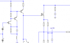
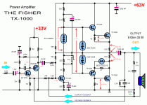
How can we define implemented GNFB type(s) on this ancient Fisher singleton audio power amp schematic ?
As real mix of CFB & VFB ? , or ?
Best Regards !
My guess would be, CFB on both wires 🙂 lets see what the experts say. The VFB-wire (as you marked it) (in my opinion) adds a current to the emitter resistor that is translated to a voltage (by the resistor), so CFB 🙂
Last edited:
Member
Joined 2009
Paid Member
I've posted a short write-up on my website. Here is a link to the doc.
CFA vs classic Lin VFA topology V1.0
I will leave this thread again to its own devices.
😎
You should turn this in to a business - it doesn't look like a hobbyist website, but it does look like a good professional site of a manufacturer that wants to sell you a CFA amplifier. And you need an 'angle' these days, setting up as the 'CFA guy' could be a differentiating factor that provides a technical reason for performance. Your site has professional looking images and a well organized structure. It raises the bar.
Last edited:
Hi Guys !
How can we define implemented GNFB type(s) on this ancient Fisher singleton audio power amp schematic ?
As real mix of CFB & VFB ? , or ?
Best Regards !
The scripting on the schematic is, in a classic sense, correct. One loop samples the output voltage, the other the output current. In the spirit of this thread, you may though call the "voltage feedback" as "current feedback", since it is fed into a low impedance node. YMMV.
Banat, where is this pic from? The amp is quite sophisticated and worth study.How can we define implemented GNFB type(s) on this ancient Fisher singleton audio power amp schematic ?
It looks like from an article rather than a service manual.
Andrew, this is an excellent article as is expected from Bonsai 🙂 It explains accurately & clearly many of the myths in the CFA/VFA debate loved by the semantic pedants.I've posted a short write-up on my website. Here is a link to the doc.
CFA vs classic Lin VFA topology V1.0
But if I may suggest some minor additions ...
I thought I had come to grips with da beloved TLAs in this forum but some of them stumped me. I read to the end before realising what MC was and I still dunno was iz TAS 😕
It would be nice to have a small section on 'simple' CFA inputs rather than promote only the evil diamond input CFA. There are enough pros & cons for 'simple' to make it a useful discussion.
Lastly, IMveryHO most of the 'faults' of CFAs are due to the 'symmetrical' topology deemed necessary by those versed in the art and these faults are not limited to CFAs.
_________
Anyone bought Self's new Power Amp book and can tell us what new evils he lays on 'symmetrical' ? 😱
Symmetrical topology -
if you look at symmetrical from another view point, it has great advantages. At least from what I think of as symmetrical topology. Namely, for distortion cancellation. Nfb or gnfb is a means to reduce distortion --- it is not cancelling distortion. With a little work, you can get all the (nonlinear) C's to cancel distortion with a symmetrical topology. Then, only small amounts of gnfb is needed to clean up the remains and stabilize the circuit parameters.
View attachment Symetrical topology for thd cancelling.pdf
Thx-RNMarsh
It would be nice to have a small section on 'simple' CFA inputs rather than promote only the evil diamond input CFA. There are enough pros & cons for 'simple' to make it a useful discussion.
Lastly, IMveryHO most of the 'faults' of CFAs are due to the 'symmetrical' topology deemed necessary by those versed in the art and these faults are not limited to CFAs.
_________
if you look at symmetrical from another view point, it has great advantages. At least from what I think of as symmetrical topology. Namely, for distortion cancellation. Nfb or gnfb is a means to reduce distortion --- it is not cancelling distortion. With a little work, you can get all the (nonlinear) C's to cancel distortion with a symmetrical topology. Then, only small amounts of gnfb is needed to clean up the remains and stabilize the circuit parameters.
View attachment Symetrical topology for thd cancelling.pdf
Thx-RNMarsh
Last edited:
The scripting on the schematic is, in a classic sense, correct. One loop samples the output voltage, the other the output current. In the spirit of this thread, you may though call the "voltage feedback" as "current feedback", since it is fed into a low impedance node. YMMV.
Yes. I agree with this characterization of cfb amps in audio. From the IC industry view this isn't a cfb amp. We can pretend it is 'because' there is a low Z port involved. But I think it would be best to call each circuit topology what they are. Maybe we need a new term for what I called, originally, a CCPP amp .. now also being called a CFA. Diamond amp, perhaps?
Thx-RNMarsh
[CCPP = Compound Complimentary Push-Pull]
Last edited:
My guess would be, CFB on both wires 🙂 lets see what the experts say. The VFB-wire (as you marked it) (in my opinion) adds a current to the emitter resistor that is translated to a voltage (by the resistor), so CFB 🙂
Hi FdW !
You are right ! ,
let`s wait to see what much more experienced members say`s !
Best Regards !
Banat, where is this pic from? The amp is quite sophisticated and worth study.
It looks like from an article rather than a service manual.
Hi kgrlee !
This schematic I have download from one Russian web site long time ago ! , but honestly I can`t remember now from which one was .
But there was only big samples of SS power amps schematics similar to this singletone one , without any following article , comments , or something else .
Best Regards !
- Home
- Amplifiers
- Solid State
- CFA Topology Audio Amplifiers