The most productive direction would be to keep following Richard's step-by-step method and try to limit our ego tendencies.
Now, some practical advice about building with CMA topologies.... which can give bad results if unaware --->
View attachment 367127
Thx-RNMarsh
Richard, that advice is a little on the wrong side when you are dealing with a power amp. The large capacitances of the outputstage form another pole which can allow the use of small cap in parralel with the feedback resistor.
There is also another condition under which a little capacitance can be allowed but lets keep such boring theory out of the thread.
My first point though is important as this can be used to obtain very high performance when designing CFA power amp.
In general the advice you posted is correct when it comes to opamp type circuits.
Manso,
As one of the unwashed masses who knows very little I would rather have what you call boring theory posted by someone who has real skill in teaching posted and discussed without making it into a fight over opposing topologies. A base of knowledge makes all of this so much more valuable for those trying to learn who are not ready to make a completed device where you are only looking at incremental improvements. This is just my opinion and you may be so far ahead this would be boring, but could you just be bored for awhile while some of us get to the exciting parts for you and some others?
Thanks,
Steven
Richard, that advice is a little on the wrong side when you are dealing with a power amp. The large capacitances of the outputstage form another pole which can allow the use of small cap in parralel with the feedback resistor.
There is also another condition under which a little capacitance can be allowed but lets keep such boring theory out of the thread.
My first point though is important as this can be used to obtain very high performance when designing CFA power amp.
In general the advice you posted is correct when it comes to opamp type circuits.
Its hard to match printed copy exactly to one's topic... the point is to be careful with wideband circuits and unintended C's (pcb layout etc) which do not show up in SIM, generally. The inverting port/mode comment is important to give some thought to.
If you have details that would help in describing the Current-Mode Perspective, please put it here.
-RNM
Last edited:
I would rather have what you call boring theory posted by someone who has real skill in teaching posted and discussed without making it into a fight over opposing topologies.
Not that I am one of those audio gurus, but I can put it in a short and sweet form for you.
When it comes to audio power amplifiers (at least as we know them) there are no "current feedback" effects, beyond 2-5%, at least not in the sense that they are outlined in the literature. That would also explain why you can get along with a little of lead compensation that manso mentioned (try that in a DSL line driver IC, set for a gain of 2).
What are herein incorrectly called CFAs are VFAs with a different input stage compared to a standard LTP. The topology of the input stage does affect the amplifier properties, in particular the slew rate (due to the "current on demand" property, which is by no means specific to CFAs). It also affects the compensation options (in particular, I see the Alexander compensation as some sort of input inclusive Miller, or perhaps Ahuja compensation).
Comparing different input stage topologies is a interesting topic, but it requires to be treated as just another design option, with the associated trade-offs. I don't think a general metric to characterize the input stage properties exists, or will ever be accepted by everybody.
Kindhornman, sorry I didnt think members with such basic knowledge in electronics participate in discussion of design. I think you need to know the basics before and this is better learnt via books. Others here know all the theory and can rant them until you die of boredom but have no hands on experience which doesnt help either.
I dont think richard has basic knowledge so he will understand my post which was addressed to him.
I dont think richard has basic knowledge so he will understand my post which was addressed to him.
Manso,
There is an inbetween. Some of us understand concepts and what lies behind the concepts but not the detailed maths. Obviously, simple ohms law etc is ok but other stuff just isn't sinking in at present.
A little explanation of the feedback cap may not go a miss. It would help me as that is exactly where I'm at in reality. I can sim a feedback cap in series with a resistor. Everything looks normal (to me) on the sims. Try it in reality and oscillation happens.
Thanks
Paul
Nice one, Elvee. But, if you want to be fair, don't kill the VSSA to begin a comparison: use my VSSA CFA sim, conform to L.C. schematic:
http://www.diyaudio.com/forums/solid-state/225747-vssa-lateral-mosfet-amplifier-6.html#post3314786
This one is not at all. Too easy to kill the bandwidth of a CFA to make-it measure like a VFA 🙂
We are not comparing as to determine which is best.... rather, to determine why one performs better and in what parameter and then... why.
It seems silly to me to 'normalize' designs before comparing. They ought to be compared as designed and then see why the differences in parameters and relate it in some way to the design perspective.
However, here, we want all info to relate to the topic. That includes topology examples. Otherwise, I stick with Bonsai in ignoring and not responding and moving on.
Thx-RNMarsh
"Comparing different input stage topologies is a interesting topic, but it requires to be treated as just another design option, with the associated trade-offs. I don't think a general metric to characterize the input stage properties exists, or will ever be accepted by everybody."
Agreed,
This is true everywhere in the reproduction chain. Everywhere in the reproduction chain from source to speakers is designed with a series of compromises,
Agreed,
This is true everywhere in the reproduction chain. Everywhere in the reproduction chain from source to speakers is designed with a series of compromises,
May I remind you that you asked for that one as a starting point:Nice one, Elvee. But, if you want to be fair, don't kill the VSSA to begin a comparison: use my VSSA CFA sim, conform to L.C. schematic:
Can you post the asc file of your sim in this thread: http://www.diyaudio.com/forums/vend...-lateral-mosfet-amplifier-30.html#post3314786 ?Could-you, please, publish or send-me your sim files and models for the VSSA sims you made ?
Because nobody seems interested to make a VFA version of it, i could try to make one myself.
I had send-you a PM
Have nice holidays,
Christophe.
It will be simpler than browsing through hundreds of posts
As I see it you get one inherent unlinearity in exchange for one/two less componentes. Ideally you had no voltage fluctuation where you inject the feedback current in a low impedance node.but as you still need the right feedback ratio, and can't drain all your power to ground then something like 10/280 ohms seems about right. Since the input node really has some impedance to ground it's also modulated voltage vise. On the other hand the circuit is simpler as you don't need the 2. set input devices that in reurn provides their own set of unlinearities.
There actually is a lot written on the topic. I would suggest, instead of speculation and questions, we do some reading by true experts in the area who are designing IC CM OpAmps. You can start with some App Notes from Intersil: # 9420.
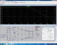
The differences can also be shown this way -->

Thx-RNMarsh
The differences can also be shown this way -->
Thx-RNMarsh
Last edited:
Here is an interesting work which might appeal to some here to unify the analysis and then compare the differences.
Thx-RNMarsh

Thx-RNMarsh
There actually is a lot written on the topic. I would suggest, instead of speculation and questions, we do some reading by true experts in the area who are designing IC CM OpAmps. You can start with some App Notes from Intersil: # 9420.
The differences can also be shown this way -->
View attachment 367229
This is an excellent way to illustrate exactly my point above. In that bunch of equations, just consider a CFA with ZF>>ZG (as in any power amplifier with a gain larger than 20dB) and see what you get. Hint: nothing but exactly the VFA equations 😛.
I think many people who have loadsa experience with VFA amps are watching this thread with interest but have yet to see pearls of wisdom. I'm saddened that some important CFA afficianados like LC have been put off and left this thread.
I don't look at amp topologies with religious fervour. If I 'favour' VFAs, its simply cos I've done most of my work with them and can eg relate sims to 'real life'.
Unlike the semantic pedants like MikeK, I like my sims to have some semblance to 'real life' ... rather than support some pet theory. I HATE suggesting circuits which I haven't burnt solder to try. I know from experience that something that looks good on paper, theory or sims is often (always?) VERY different in 'real life'.
But what I'm really looking for is stuff that I can't get with my previous efforts. In this case, the potential advantage is noise performance .. prompted by David Zan's requirements. Another is simplicity. With respect to Bonsai, his designs are too complicated for my small brain.
LC's VSSA or simple variants give me these characteristics. Diamond inputs lose them.
I've done some work on something very similar to VSSA and compared it to a simple VFA that I've worked on for a long time.
I have to say, from now on, I have to look at CFAs very closely indeed.
More to come.
Richard, that advice is a little on the wrong side when you are dealing with a power amp. The large capacitances of the outputstage form another pole which can allow the use of small cap in parralel with the feedback resistor.
Nonsense, the output stage pole has nothing to do with the ability to support a little lead compensation. The fact that a so-called "audio CFA" with a closed loop gain > 20dB degenerates to a classic VFA behavior does.
If you disagree, prove your point and show what exactly has the output stage pole(s) to do with the lead compensation (other than in some pathological case with the ULGF anywhere close to that pole). Wait, that would bore the audience, right?
Manso,
There is an inbetween. Some of us understand concepts and what lies behind the concepts but not the detailed maths. Obviously, simple ohms law etc is ok but other stuff just isn't sinking in at present.
A little explanation of the feedback cap may not go a miss. It would help me as that is exactly where I'm at in reality. I can sim a feedback cap in series with a resistor. Everything looks normal (to me) on the sims. Try it in reality and oscillation happens.
Thanks
Paul
Does this cap cause oscilation on your amp ??
You mentioned some peaking in closed loop respons in your thread.
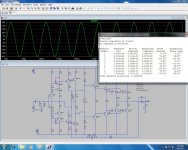
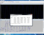
Some further proof of good performance from CFA.
Simplified schematic for now, Ill include the servo and optimize as I recall the exact details as the design is close to 20 years old. These are sim results although the real amp showed figures not far off. The cascodes can be ommited if high voltage transistors are used and THD is improved without them.
THD20 at 100W .000680%
THD1k at 100W .000202%
Phase margin 84 degrees
Gain margin 14 Degrees
ULGF 7 Mhz
I experimented a little with Edmonds DTMC and indeed performance is bettered but Ill only post details after confirming that the amp is stable using it.View attachment 367265
Attachments
Some further proof of good performance from CFA.
THD20 at 100W .000680%
THD1k at 100W .000202%
Phase margin 84 degrees
Gain margin 14 Degrees
ULGF 7 Mhz
Good luck with that.
Good luck with that.
No luck needed, the design was in production for 15 years 😛
Some have real hands on design experience unlike yourself that can only quote the theory from books.
Last edited:
- Home
- Amplifiers
- Solid State
- CFA Topology Audio Amplifiers