Hi Russell,
I use the German flux paste - see the picture. Something pretty similar in Mouser stock:
>NO CLEAN FLUX PASTE<
With regards to the FETs - good point. I think, I will have to remove a couple of the output plugs to be able to use some lower angle while soldering them, just to have more "massive" contact with the iron. I use a regulated-temperature iron, so normally, if I slightly increase it - it's enough for soldering such "areas".
Cheers,
Valery
Here's one with solder in it. It works good with an iron or in an oven.
SMD291AX10 Chip Quik Inc | SMD291AX10-ND | DigiKey
Use roughly twice as much as it looks like you would need and it works out perfectly. This is what I use in the oven. I've never bothered with stencils. Solder mask takes care of any shorts on close leads.
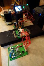
SMT FETs from Mouser, Shuntie PCBs and some parts for Shuntie, ordered locally - all came in today  Looking forward to the soldering evening 😛
Looking forward to the soldering evening 😛Hi Sam, it's possible to modify the OPS for N-channel only - I will drop the schematic update - but it will slightly suffer from additional distortion - not too much though, as the front-end is a relatively high loop gain one.
Cheers,
Valery
Thank you, Valery. This news sounds great, and if the increased distortion is low order or even harmonics, I am sure the amp will sound fantastic.
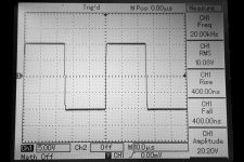
Done, tested!
OK. Soldered the FETs, pluged in, measured, listened - perfect!
Both channels are exactly the same. Surprise - no output "plop" at power on. Practically zero offset (some millivolts) right from the start. VAS FETs are very lightly warm.
Excellent Great experience 😛
Guys, who are interested in building those - green light now 😉
No energy for Shuntie tonight - will solder them in the nearest days.
Cheers,
Valery
OK. Soldered the FETs, pluged in, measured, listened - perfect!
Both channels are exactly the same. Surprise - no output "plop" at power on. Practically zero offset (some millivolts) right from the start. VAS FETs are very lightly warm.
Excellent
Great experience 😛Guys, who are interested in building those - green light now 😉
No energy for Shuntie tonight - will solder them in the nearest days.
Cheers,
Valery
Attachments
Cool. Parts arrived today. Are Gerbers available?
In your mailbox 😉
Everything is easy to get here for this.😀 For those new to SMD, buy a syringe of solder paste and cook it in a toaster oven. Touch it up with an iron later. Much easier and components actually align themselves as they bake. Data sheets always have baking instructions.
Are you sure about that syringe?
I think mine would melt.
Are you sure about that syringe?
I think mine would melt.
Don't cook the syringe! 🙂
Cook the boards with solder paste (from the syringe) and the parts.
Although, I did it the "hard" way - soldered with my iron, using the loupe...
Just noticed an interesting thing - didn't really notice it yesterday.
VAS runs at the higher quiescent current, than the one in TH version.
This one runs at 28mA now. Both channels. Well, fine with me, I don't even want to decrease it, OPS bias pot has got enough range to adapt to that and with such current it drives the OPS MOSFETS perfectly - their high input capacitance does not really matter any more.
But why? All the values are exactly the same in TH and SMT versions respectively. Must be some differences in Vbe / Vgs between the TH and SMT versions of the transistors.
Well, Nelson Pass runs those fets at 40mA. No problem. But I did not expect an increase for more than twice as much, comparing to the initial TH version...
Plays beautifully anyway 😉
Hi Sam, it's possible to modify the OPS for N-channel only - I will drop the schematic update - but it will slightly suffer from additional distortion - not too much though, as the front-end is a relatively high loop gain one.
Cheers,
Valery
Bump!
Thanks!
Nice work Valery!Just noticed an interesting thing - didn't really notice it yesterday.
VAS runs at the higher quiescent current, than the one in TH version.
This one runs at 28mA now. Both channels. Well, fine with me, I don't even want to decrease it, OPS bias pot has got enough range to adapt to that and with such current it drives the OPS MOSFETS perfectly - their high input capacitance does not really matter any more.
But why? All the values are exactly the same in TH and SMT versions respectively. Must be some differences in Vbe / Vgs between the TH and SMT versions of the transistors.
Well, Nelson Pass runs those fets at 40mA. No problem. But I did not expect an increase for more than twice as much, comparing to the initial TH version...
Plays beautifully anyway 😉
Hi Valery,
I sent the gerbers to my board house for pricing. The boards measure 7.6cm x 10.16cm. Anything over 10cm and the price almost doubles. Is it possible to reduce the footprint by 1.6mm?
Thanks, Terry
I sent the gerbers to my board house for pricing. The boards measure 7.6cm x 10.16cm. Anything over 10cm and the price almost doubles. Is it possible to reduce the footprint by 1.6mm?
Thanks, Terry
Hi Valery,
I sent the gerbers to my board house for pricing. The boards measure 7.6cm x 10.16cm. Anything over 10cm and the price almost doubles. Is it possible to reduce the footprint by 1.6mm?
Thanks, Terry
No problem, done.
Bump!
Thanks!
Hi Sam, please see attached. A simple phase inverter and we've got a quasi-complementary topology, using N-channel MOSFETs only.
Cheers,
Valery
Attachments
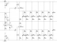
Thank you, Valery. I will start laying out the PCB. I believe one can play with the value of R65 and even parallel a Diode and Cap for optimal performance. Is only Q19 to be mounted on one of the Output MOSFETs and is LED5 a Red one? Thanks again.
Thank you, Valery. I will start laying out the PCB. I believe one can play with the value of R65 and even parallel a Diode and Cap for optimal performance. Is only Q19 to be mounted on one of the Output MOSFETs and is LED5 a Red one? Thanks again.
Yes, the LED is the red one. Q19 is mounted on the local heatsink with the drivers (Q30, Q31), Q23 is mounted on the main heatsink with all the MOSFETs. It's not necessary to mount it right on one of the MOSFETs - just touch the heatsink. I recommend to use the original Slewmaster layout as a basis for your PCB development - output section's arrangement is good there. Just modify the fragments that have changed (this is what I would do).
You can play with the value of R65 and even parallel a Diode and Cap for optimal performance, however it simulates pretty well even as is.
Cheers,
Valery
- Status
- Not open for further replies.
- Home
- Amplifiers
- Solid State
- CF-FET V2.0 front-end - going high-tech (SMD)