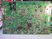
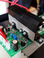
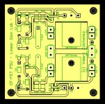
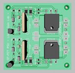
OK, the first one is done except the VAS MOSFETs - still waiting for Mouser to deliver. All the rest went pretty cool (the board is not cleaned from the flux yet). Got a jelly flux with very thin applicator - very useful, as it pretty much holds the part in place before it melts (the flux, not the part 😀). Also had to use a magnifying glass - especially when soldered 0603-package parts 🙂
So - waiting for the FETs, soldering the second channel board
Looking good so far! I see you are soldering the hard way. An oven is much easier.

Well, I will probably come to the oven technology some day - will ask you some questions then 😉
The surface tension of the molten solder does all the alignment of the parts for you. You just need to get the lead touching the appropriate pad and the solder does the rest. I hated SMT until I figured that out.
Hi Valery,
Looks good, hint, i use no clean, glow core solder.
I try to stick with 1210/1206/0805 as they are the easiest. I can do them with out a 10x jewelers loop or magnifier and a steady hand.
13368 AIM | Mouser
I have been doing smt since the 80's, when I worked for Motorola and have yet to need an oven/stencil/paste for DIY assy. I do own a Sparkfun hot air machine however. Even with an oven/stencil/paste, accurate placement of fine pitch smt is the issue IMO.
For passive removal, two fine tipped irons is the easiest way to go. That and some solder wick.
Hand soldering of the newer QFN/DFN package is a challenge 🙂 but I have figured out that you have to modify the solder mask to open it so that you can get the iron to flow solder into the land area. Alignment is the real problem, getting that first land/joint to solder up.
Cheers Rick
Last edited:
Hi Rick,
Thank you for advise. I'm thinking about a dual-iron soldering station - exactly for the purpose of removing the parts when needed.
QFN/DFN must be easier with the oven technology, Jeff mentioned above - the pins are sort of too far under the package. Well, next level for me 🙂
Cheers,
Valery
Thank you for advise. I'm thinking about a dual-iron soldering station - exactly for the purpose of removing the parts when needed.
QFN/DFN must be easier with the oven technology, Jeff mentioned above - the pins are sort of too far under the package. Well, next level for me 🙂
Cheers,
Valery
Hi everyone,
I have lots of free advise 🙂 lots of experiences, good and bad !!
Hakko's are top dog, from what I have used, at home I use two Weller's, why? because they were free 🙂 one temp controlled and the other change tip for temp control.
Even a hot plate would work for the paste method and some removal/reflow. Just got to watch the dwell/soak time and temp of course.
Oh ya, use Pb/Sn solder for hand assy. Leave no-Pb for the contract guys.
My stuff, should last forever, never see a land fill 🙂 need some spare parts of course, since they go obsolete, so fast these days.
At work (McDATA), we had a Leica stereo microscope, nice, but not in my DIY budget, that and a Agilent 10G scope 🙂
I remember at HP, when they bought our dev lab from Alcatel. We setup a new lab (1995), HP bought an auto hot air re-work station for our lab, to use for BGA/qfp/smt rework 😱. It was a massive thing that sat in the corner, a real white elephant. Needed compressed air/vacuum too. We EE's shook our heads, but the Mfg manager insisted = 😱. IIRC, it was only used a few times, for the demo/training. We got the Contract Mfg, Celestica(IBM) to do the BGA re-work, as it was, they had a 4-pi xray machine 🙂
With the lab setup, at HP, it was like kids in a candy store, we got to get any HP test equipment that we wanted, within reason, of course = the good old days. Then they sold us (lab) to McData(Brocade), just like livestock 😱 got to setup yet another lab ...
In the end, the way I look at it, sorting/placing the comps takes the most time as it is.
Leica and Fuji pick n place, in the nice to have category 🙂
For you enjoyment, a pic of my last big project, (portable radio/media player) still working on software for it, now looking at FT800 graphics/touch screen display. Big leap from a 4x40 character LCD.
Cheers Rick
Probably more $, just get another one.dual-iron soldering station
I have lots of free advise 🙂 lots of experiences, good and bad !!
Hakko's are top dog, from what I have used, at home I use two Weller's, why? because they were free 🙂 one temp controlled and the other change tip for temp control.
Even a hot plate would work for the paste method and some removal/reflow. Just got to watch the dwell/soak time and temp of course.
Oh ya, use Pb/Sn solder for hand assy. Leave no-Pb for the contract guys.
My stuff, should last forever, never see a land fill 🙂 need some spare parts of course, since they go obsolete, so fast these days.
At work (McDATA), we had a Leica stereo microscope, nice, but not in my DIY budget, that and a Agilent 10G scope 🙂
I remember at HP, when they bought our dev lab from Alcatel. We setup a new lab (1995), HP bought an auto hot air re-work station for our lab, to use for BGA/qfp/smt rework 😱. It was a massive thing that sat in the corner, a real white elephant. Needed compressed air/vacuum too. We EE's shook our heads, but the Mfg manager insisted = 😱. IIRC, it was only used a few times, for the demo/training. We got the Contract Mfg, Celestica(IBM) to do the BGA re-work, as it was, they had a 4-pi xray machine 🙂
With the lab setup, at HP, it was like kids in a candy store, we got to get any HP test equipment that we wanted, within reason, of course = the good old days. Then they sold us (lab) to McData(Brocade), just like livestock 😱 got to setup yet another lab ...
In the end, the way I look at it, sorting/placing the comps takes the most time as it is.
Leica and Fuji pick n place, in the nice to have category 🙂
For you enjoyment, a pic of my last big project, (portable radio/media player) still working on software for it, now looking at FT800 graphics/touch screen display. Big leap from a 4x40 character LCD.
Cheers Rick
Attachments
Hi everyone,
Probably more $, just get another one.
I have lots of free advise 🙂 lots of experiences, good and bad !!
Hakko's are top dog, from what I have used, at home I use two Weller's, why? because they were free 🙂 one temp controlled and the other change tip for temp control.
Even a hot plate would work for the paste method and some removal/reflow. Just got to watch the dwell/soak time and temp of course.
Oh ya, use Pb/Sn solder for hand assy. Leave no-Pb for the contract guys.
My stuff, should last forever, never see a land fill 🙂 need some spare parts of course, since they go obsolete, so fast these days.
At work (McDATA), we had a Leica stereo microscope, nice, but not in my DIY budget, that and a Agilent 10G scope 🙂
I remember at HP, when they bought our dev lab from Alcatel. We setup a new lab (1995), HP bought an auto hot air re-work station for our lab, to use for BGA/qfp/smt rework 😱. It was a massive thing that sat in the corner, a real white elephant. Needed compressed air/vacuum too. We EE's shook our heads, but the Mfg manager insisted = 😱. IIRC, it was only used a few times, for the demo/training. We got the Contract Mfg, Celestica(IBM) to do the BGA re-work, as it was, they had a 4-pi xray machine 🙂
With the lab setup, at HP, it was like kids in a candy store, we got to get any HP test equipment that we wanted, within reason, of course = the good old days. Then they sold us (lab) to McData(Brocade), just like livestock 😱 got to setup yet another lab ...
In the end, the way I look at it, sorting/placing the comps takes the most time as it is.
Leica and Fuji pick n place, in the nice to have category 🙂
For you enjoyment, a pic of my last big project, (portable radio/media player) still working on software for it, now looking at FT800 graphics/touch screen display. Big leap from a 4x40 character LCD.
Cheers Rick
I use two solder stations for reworking too. The tweezers look handy for resistors and caps but a big blob of solder and a large tip make short work of them. When it comes to peeling an IC off a big iron is the only thing that has worked for me.
Hi everyone,
Probably more $, just get another one.
I have lots of free advise 🙂 lots of experiences, good and bad !!
Hakko's are top dog, from what I have used, at home I use two Weller's, why? because they were free 🙂 one temp controlled and the other change tip for temp control.
Even a hot plate would work for the paste method and some removal/reflow. Just got to watch the dwell/soak time and temp of course.
Oh ya, use Pb/Sn solder for hand assy. Leave no-Pb for the contract guys.
My stuff, should last forever, never see a land fill 🙂 need some spare parts of course, since they go obsolete, so fast these days.
At work (McDATA), we had a Leica stereo microscope, nice, but not in my DIY budget, that and a Agilent 10G scope 🙂
I remember at HP, when they bought our dev lab from Alcatel. We setup a new lab (1995), HP bought an auto hot air re-work station for our lab, to use for BGA/qfp/smt rework 😱. It was a massive thing that sat in the corner, a real white elephant. Needed compressed air/vacuum too. We EE's shook our heads, but the Mfg manager insisted = 😱. IIRC, it was only used a few times, for the demo/training. We got the Contract Mfg, Celestica(IBM) to do the BGA re-work, as it was, they had a 4-pi xray machine 🙂
With the lab setup, at HP, it was like kids in a candy store, we got to get any HP test equipment that we wanted, within reason, of course = the good old days. Then they sold us (lab) to McData(Brocade), just like livestock 😱 got to setup yet another lab ...
In the end, the way I look at it, sorting/placing the comps takes the most time as it is.
Leica and Fuji pick n place, in the nice to have category 🙂
For you enjoyment, a pic of my last big project, (portable radio/media player) still working on software for it, now looking at FT800 graphics/touch screen display. Big leap from a 4x40 character LCD.
Cheers Rick
Wow! Impressive 🙂
I also like to design something on the edge of hardware and software. When it comes to implementation - SMT definitely helps

FT800 is a cool chip - I've seen some Arduino-compatible display boards, based on it.
Jeff - I think, it will be logical to design the possible next version of the control board, using SMT parts where appropriate, making it even more compact 😉
Rick - I'm talking about this ATMega328-based joint development >HERE<
Thanks Valery. SMT saves cost in pcb area and usually makes for a quiter/compact design with added benefit for auto assembly. It was never intended for hand soldering.
I have been following your protection thread too. Sounds like you have it working just fine. I have noticed that you are not making the source code available, but I do understand your reasons for not doing so. I have not released my portable code to the world either but I would consider to collaborate, depending on what it is.
I have a design which has a aux transformer, to power a controller. It has a soft-start ckt/relay for the big power amp transformer.
I decided 2-3 years ago not to use Arduino, because I wanted to reduce my footprint size to one small 4-layer pcb and use xmega in the "au" package. We can trade ideas on your protect board thread.
Thanks Valery. SMT saves cost in pcb area and usually makes for a quiter/compact design with added benefit for auto assembly. It was never intended for hand soldering.
I have been following your protection thread too. Sounds like you have it working just fine. I have noticed that you are not making the source code available, but I do understand your reasons for not doing so. I have not released my portable code to the world either but I would consider to collaborate, depending on what it is.
I have a design which has a aux transformer, to power a controller. It has a soft-start ckt/relay for the big power amp transformer.
I decided 2-3 years ago not to use Arduino, because I wanted to reduce my footprint size to one small 4-layer pcb and use xmega in the "au" package. We can trade ideas on your protect board thread.
I've broken down the ATmega on his board design to save size too. I'm designing a full SMT version with USB interface and possibly a network port right now.
I am sure you have your reasons for a USB and/or LAN port interface but I am not sure why they are required for a power amp protection circuit design and how it improves functionality? If I think a bit more, I do use the FT232RL USB interface for the xmega bootloader in the portable design.
I'm adding it for ease of programming and possible future datalogging or other options. Valery's hybrid designs come up with some odd requirements for a control circuit sometimes. Supplies need to be started in the right order and at the right time, ect.
I have not studied the design thoroughly enough to know why this is so.Supplies need to be started in the right order and at the right time, etc.
edit: i assume you mean that you have to turn on the power relay to the PA transformer first, wait a short period 1-2 s and then turn on the soft-start relay which shorts out the primary current limit resistors.
Just so that I am on the same page, I am looking at Linear Gain Lab PIC driven power amp protection v1.1. I also see v2,3 schematics, although I do not notice any difference.
Last edited:
What Jeff means with regards to my hybrid designs - there are some tubes there, so we use an additional control channel for heating them up before even starting inrush, so the soft-start sequence becomes more complicated, with some intermediate checks of some sensors before moving on to the next step of the sequence.
On request from Marc (Idefixes)
Hi Marc,
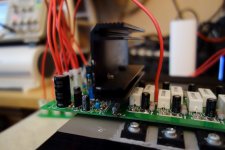
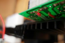
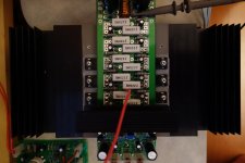
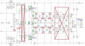
Here is my IRFP-based OPS. It is based on original Slewmaster PCBs. Sorry, I was too lazy for re-drawing it completely, so just replace BJTs with IRFP240/9240. Pinouts are fully compatible (BCE = GDS). I use two 1K resistors in parallel between the drivers' emitters, but you can use one 500R one (1W).
Thanks to Jason Kuetemann for assistance in adjustment of the spreader tempco for matching the one for IRFPs (adding the red LED was his idea).
You can use all 5 pairs if you like (I used 3 of them as it was enough for the purpose at that time). C10 (1uF) stays in place.
Cheers,
Valery
Hi Marc,
Here is my IRFP-based OPS. It is based on original Slewmaster PCBs. Sorry, I was too lazy for re-drawing it completely, so just replace BJTs with IRFP240/9240. Pinouts are fully compatible (BCE = GDS). I use two 1K resistors in parallel between the drivers' emitters, but you can use one 500R one (1W).
Thanks to Jason Kuetemann for assistance in adjustment of the spreader tempco for matching the one for IRFPs (adding the red LED was his idea).
You can use all 5 pairs if you like (I used 3 of them as it was enough for the purpose at that time). C10 (1uF) stays in place.
Cheers,
Valery
Attachments
Shuntie
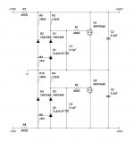
For high-quality builds I have designed a high-precision shunt regulator for the front-end. Not tested live yet, however simulation shows ripple reduction for more than 100db. Sort of "virtual battery".
The idea is to power the OPS with +/-70V, then the rails are slightly filtered with the cap multipliers on OPS boards and go to the shunt regulator. Front-ends are powered with heavily filtered +/-50V from Shuntie.
Cheers,
Valery
Attachments
Combination of TH and SMD...
Nice. Would be interested in GB boards when and if ...
Nice. Would be interested in GB boards when and if ...
I have ordered a couple of boards - let me test it before I send you the gerbers.
- Status
- Not open for further replies.
- Home
- Amplifiers
- Solid State
- CF-FET V2.0 front-end - going high-tech (SMD)