It just dawned on me that there is no trimmer. How do you adjust the output?
I don't 🙂
You can reduce the output current by reducing R11, R12. However, MOSFET VAS likes to run at high current (15-25mA). Tubsumo OPS handles it with ease. IRFP-based Slewmonsters also work fine with it.
OK I'll just use it with the Tubsumo OPS. My FET Slew OPS has problems. I'll have to get to the bottom of that one day soon.
Thanks, Terry
Thanks, Terry
OK I had a few minutes to do some testing. The first channel fired right up. Looks very good. Of course the second channel does not. It starts off with about 1v offset but then climbs to -24v after a few seconds. So obviously something is not attached somewhere. I have now discovered that trying to take measurement on a surface mount board takes a little different approach. The electronic caps completely hide the pads and it is slim pickings for measuring points. I know this is the direction things are heading but I'm not a fan yet.
No special tools needed. You pop it in the oven and set the temp to 125C. After 2 minutes you turn it up to 225C. Once it reaches 225, shut the oven off and open the door. Leave it sit until it's cool. This can't be done with through hole caps on the board though.
OK I had a few minutes to do some testing. The first channel fired right up. Looks very good. Of course the second channel does not. It starts off with about 1v offset but then climbs to -24v after a few seconds. So obviously something is not attached somewhere. I have now discovered that trying to take measurement on a surface mount board takes a little different approach. The electronic caps completely hide the pads and it is slim pickings for measuring points. I know this is the direction things are heading but I'm not a fan yet.
Ah, I have also thought about measurements convenience - my idea is to make some special "measurement pads" at the places where some measurement would be useful 🙂
OK I repositioned Q3 and now both boards are working. They look perfect until I add a load and then I see oscillation on the bottom of the wave form. Exactly the same on both channels.
I just got introduced to this little gem for your Uno. Nothing like automation 🙂No special tools needed. You pop it in the oven and set the temp to 125C. After 2 minutes you turn it up to 225C. Once it reaches 225, shut the oven off and open the door. Leave it sit until it's cool.
Rocket Scream | Reflow Controller Shield
Certainly does not hurt to have some test-point symbols/footprints/vias in your libraries 🙂Ah, I have also thought about measurements convenience - my idea is to make some special "measurement pads" at the places where some measurement would be useful
Last edited:
OK I repositioned Q3 and now both boards are working. They look perfect until I add a load and then I see oscillation on the bottom of the wave form. Exactly the same on both channels.
OK, this is caused by OPS, I also had a little bit of it in one channel initially.
As these boards are wide bandwidth, they require more precise match of the output FETs' input capacitance.
Change the gate stoppers (two resistors) on 2SK1058 side (R4, R5) from 470R to 330R.
This has solved the ptoblem for me completely.
I just got introduced to this little gem for your Uno. Nothing like automation 🙂
Rocket Scream | Reflow Controller Shield
Certainly does not hurt to have some test-point symbols/footprints/vias in your libraries 🙂
Ben Heck/Element 14 has a little video on automating the oven. I tried one a couple years ago. It worked good a couple of times. I got called away mid cycle one time and came back to an office full of smoke. It stayed on high and cindered the board. My office stunk for a couple months and I've been running manual ever since.
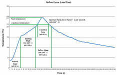
Here's a good chart to explain how to cook a board. That little peak at the top for 60 seconds is when all the magic happens. All the solder on the board becomes liquid at that point and all the parts float on it and align themselves because of the surface tension of the solder. This chart is a little hotter than most but the parts are very forgiving. Other than one board turned to ash and a couple through hole electrolytics, I've never damaged a part in the oven. If you have a flaky board that does strange stuff when you bump it, paint it with liquid flux and run it through this same cycle. It will reflow the board and fix any bad solder joints. This was standard procedure for 301 Dishnet satellite boxes when they would loose signal intermittently. The BGA chip for the LNB would crack off the board from heat cycling.
Attachments
Funny, I remember at Motorola, a new "green" mech eng ran, for whatever crazy reason, a fr4 (epoxy/glass) pcb through the IR oven/line setup for ceramic substrate. smoked the whole factory, fire rails,cops, sick employees, we got the afternoon off, paid of course 🙂
It is like the old bread toaster, when are they going to invent a smoke detector option?, right know it is my trusty smoke alarm.
It is like the old bread toaster, when are they going to invent a smoke detector option?, right know it is my trusty smoke alarm.
Last edited:
Sorry - even to 300R
Hi Valery,
That worked. I temporarily soldered 1k resistors in parallel with the 470Rs. I see just a slight thickening of the top of a square wave now. Also the higher frequency squares are more rounded now but that oscillation is gone from the bottom of the waves. I just got through listening to some Gerry Mulligan at volume through those JBLs. It felt like I was sitting amongst the band. Thing of beauty!
Thanks for another great design.
I have some extra boards for those interested.
Blessings, Terry
Hi Terry,
Great! I'm glad you like it 🙂
I also find it being very transparent and natural-sounding, handling highly dinamic scenes with ease.
Cheers,
Valery
Great! I'm glad you like it 🙂
I also find it being very transparent and natural-sounding, handling highly dinamic scenes with ease.
Cheers,
Valery
Here's a good chart to explain how to cook a board. That little peak at the top for 60 seconds is when all the magic happens. All the solder on the board becomes liquid at that point and all the parts float on it and align themselves because of the surface tension of the solder. This chart is a little hotter than most but the parts are very forgiving. Other than one board turned to ash and a couple through hole electrolytics, I've never damaged a part in the oven. If you have a flaky board that does strange stuff when you bump it, paint it with liquid flux and run it through this same cycle. It will reflow the board and fix any bad solder joints. This was standard procedure for 301 Dishnet satellite boxes when they would loose signal intermittently. The BGA chip for the LNB would crack off the board from heat cycling.
Still sounds like a little bit of "mystery" to me 😉
Jeff, can you please drop a link to some appropriate oven, so that I better understand what to look for...
Terry take a picture from your solder paste.Jeff, do you cook the SMD electrolytics too?
- Status
- Not open for further replies.
- Home
- Amplifiers
- Solid State
- CF-FET V2.0 front-end - going high-tech (SMD)