@lineup , loopgain plots construction is as easy as ABC. Please read what we are saying to you. Read it, do not find excuses, please.
My 12 cents:

This is an amplifier under test. Sine source is placed into feedback loop, as shown in the red rectangle. Input is shorted.
Then you plot V(out)/V(A) gain:

My 12 cents:
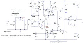
This is an amplifier under test. Sine source is placed into feedback loop, as shown in the red rectangle. Input is shorted.
Then you plot V(out)/V(A) gain:

Lineup, the last version of Micro-Cap still is available. It can provide loop gain, stability, phase and more plots. The files include enough examples of "famous amps of the past" which you can study, to get a much better grasp than you have now. The examples come with indications "what to run".
http://web.archive.org/web/20230214034946/http://www.spectrum-soft.com/download/download.shtm
http://web.archive.org/web/20230214034946/http://www.spectrum-soft.com/download/download.shtm
You can measure separately both the TMC loop and the global loop. I usually focus on the global loop.You're right.
Also, not only the output side but also the input side affects the loop gain. I recommend also measuring the loop gain with the input open not only short.
Generally, input has a capacitance of several tens of pF, there will be no problem.
BTW everyone
is this wrong?
I have not received a reply from PMA. Bonsai is also connected to the feedback network side, what do you think?
HAYK previously measured the loop gain of only the TMC part, what do you think?
By global loop, do you mean the one that includes TMC?
In other words, should the pier resistance be on the return resistance side or on the output side?
I call what I measure by connecting it to the output side as global feedback. Maybe I should have called it a major loop.
In any case, if you connect it to the feedback resistor side, you measure the loop gain that is the sum of the TMC loop and the major loop.
I am checking the stability by connecting it to the output side.
Yes, I measure the sum of the two loops per my earlier post with the plot picture. To measure just the TMC loop, close the main loop and insert the stimulus in the 1k resistor going to the TMC caps (output side of the resistor). You can basically check any loop like this.
It did not work for me 🙁@lineup , loopgain plots construction is as easy as ABC. Please read what we are saying to you. Read it, do not find excuses, please.
My 12 cents:
View attachment 1247932
This is an amplifier under test. Sine source is placed into feedback loop, as shown in the red rectangle. Input is shorted.
Then you plot V(out)/V(A) gain:
View attachment 1247939
Would you be willing to show what you have exactly done? To find out why it did not work, because the principle is universal.
Hi. I tuned the amplifier as best I could, removed the input filter, and shorted the feedback using a huge capacitor. You can limit the input voltage by using an additional amplifier with tone controls connected to buses with a voltage of about 6 volts. The coil adds two zeros to the THD, but it really messes up the clip.
Attachments
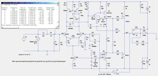
My posted circuit has Open Loop Gain 97.8dB/1kHz. Decreases to 53.8dB/20kHz
Closed Loop Gain is 22.4dB
Closed Loop Gain is 22.4dB
Last edited:
Think I am a bit on the way.Would you be willing to show what you have exactly done? To find out why it did not work, because the principle is universal.
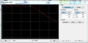
I added signal into the feedback resistor.
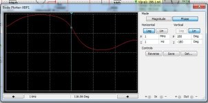
Then I used an instrument called Bode plotter to see the output.
Gives 2 curves: Magnitude and Phase.
So I was able to see the OLG curve. But phase look very strange.
Lineup, please post it then we can discuss your results. It’s good that you are trying this 👍
I created a simple 'Open Loop Gain and Phase simulation' for dummies step-by-step presentation.
Images and individual steps (1 asc file + image(s) for each step) attached in one zip file.


Etc....
All 11 steps/slides in the zip file.
Open each asc file one by one and read comments at the bottom, and also look at corresponding image file.
You can actually run simulations in each step.
I hope I didn't miss anything.
Images and individual steps (1 asc file + image(s) for each step) attached in one zip file.
Etc....
All 11 steps/slides in the zip file.
Open each asc file one by one and read comments at the bottom, and also look at corresponding image file.
You can actually run simulations in each step.
I hope I didn't miss anything.
Attachments
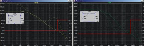
Here is the magnituds and the phase results of latest posted schematic.Lineup, please post it then we can discuss your results. It’s good that you are trying this 👍
It goes from 1Hz to 1MHz
Attachments
Minek123
Thanx for your " Open Loop Gain and Phase simulation' for dummies"
Great job !
Thanx for your " Open Loop Gain and Phase simulation' for dummies"
Great job !
Progress! Thats excellent!Here is the magnituds and the phase results of latest posted schematic.
It goes from 1Hz to 1MHz
your gain and phase plots have the right shape, but it’s the details outlined below that we have to dig into now.
Can you add the plot axis scales so we can look at actual gain and phase mag? We want to look at where the gain plot crosses the 0 dB point on the axis (unity loop gain frequency aka ULGF) and then on the phase plot we have to look at the the phase margin at the ULGF and then gain margin.
👍
Last edited:
Hi All
Has anyone checked whether the latest version of the diagram (#388 by Lineup) is correct/stable and ready to build a prototype?
Is further work/simulations still ongoing?
BTW Can anyone add the .asc file of latest version ?
Has anyone checked whether the latest version of the diagram (#388 by Lineup) is correct/stable and ready to build a prototype?
Is further work/simulations still ongoing?
BTW Can anyone add the .asc file of latest version ?
- Home
- Amplifiers
- Solid State
- Cello One. Good Amplifier 15 Watt with TMC and Laterals