A RC after the output devices on each rail should help a lot. Something like a R of 10 to 22 and a C of 220u to 1000u. Smaller cap with bigger R makes the PCB easier to design at the expense of some headroom.
Funny, I've never had this problem - I use a 4.7Ohm 2510 SMD resistor. How do you get enough ground current flowing to pop at 1/2 or 1 W resistor without a serious fault somewhere else in your system?I do not like that inter-ground resistor very much, after I have experienced serious failures of such amplifiers when this resistor was burnt by error ground current. I prefer two separated power supplies for 2 channels and the left and right ground connected on the input connectors. Just at this one and only point.

The BW limiting filter is best set at 10-15x the audio BW - 900 kHz is too wide IMV. It's there to prevent RF ingress, but also to make sure the front end is not exposed to rise/fall times that will drive the LTP out of its linear operating range. The degeneration you have put in the LTP helps with this, but you still need to BW limit the front end 🙂I will see what I can do. Maybe make R21 2.2k.
As for now the lowest frequency is 300kHz. With pot at 50%.
The upper frequency now without input filter is like 900kHz.
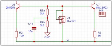
Adding to this, would splitting the 6.8k R7 and bypassing the midpoint with a 10u to 47u cap to the negative rail help with PSRR?
Here's a illustration of what I was referring to in Post #155. You can tinker with values for the cap to see what improvement (if any) to PSRR it makes.
Attachments
@ Lineup: The RC is 10 ohm with 22,000 uF (22m in ucap jargon). These days, fairly cheap.
The downside being if this placed on the PCB, it is a rather large component. Normally, we'd see a CRC filter used in the power supply, with the R lower at 0.1R to 0.5R.
Heavy pos overdrive at inputr will grill U10😒
What about adding a current limiting resistor placed between the collector and ground. Wouldn't this mitigate it to some extent?
It would - but all in all a work around a design flaw. I propose to rework that area.
Last edited:
U11 is also dangeourously unlimited, both U10 and U11 should have a serial 4.7k in their collectors, that s not as ugly as one would think, voltage drop is very low and AC characteristics of the circuit is not influenced.Heavy pos overdrive at input will grill U10😒
Edit : A 2.2k is also necessary between the voltage reference U12 and the base of U7, this way 250uA through R7 is enough to have the relevant voltage at U12 on start up, so the amp is stabilised DC wise at a lower supply voltage.
A RC after the output devices on each rail should help a lot. Something like a R of 10 to 22 and a C of 220u to 1000u. Smaller cap with bigger R makes the PCB easier to design at the expense of some headroom.
As I said, PSRR was 58dB at the positive. A little more decibel at the negative.@ Lineup: The RC is 10 ohm with 22,000 uF (22m in ucap jargon). These days, fairly cheap.
When I added filters 1000u+33ohm the PSRR is 82dB at 100Hz and 100dB at 1kHz
TLV431 is prcise and is not very affected of current variations.Here's a illustration of what I was referring to in Post #155. You can tinker with values for the cap to see what improvement (if any) to PSRR it makes.
Now that I added supply filters it is okay.
The BAV21 will stop that from happeningHeavy pos overdrive at input will grill U10😒
I totally agree and would never install a volume pot at the amplifier input.I'd suggest leaving the pot (R22) out. Most designs are not specified with a volume Pot. This seems like a very builder specific decision. The builder can always add it if they want.
You made a point, I was wrongI don't see how U10 in latest schematics #158 is in danger, at around 1mA or little bit above it is already fully engaging the VAS transistor U6 and the Baker clamp comes in.
The LTP can't pull more than 5,3 mA which is dictated by the CCS.
1mA * 20V = 20mW through U10.
With neg output clipping U7 saturates and thus shorts the ref voltage delivered by U12. A baker clamp diode around U7 fixes this roughly. A base series resistor of 330R before U7 shows better results.
Last edited:
Ultimately one winds up designing and building an opamp with discrete components that improves PSR quite a bit but is rather complicated because the advantage of "on same chip" is absent. Hence the simplest solution is to apply an audio opamp in a way that global GNFB provides the required PSR plus improvement re distortion.There may be smarter ways than such bulky caps to improve PSSR. But if you are in for a simple design 68dB @50hz might do well. If you want to squeeze it for ultimate performance - there is much more to do.
- Home
- Amplifiers
- Solid State
- Cello One. Good Amplifier 15 Watt with TMC and Laterals