I don't see how U10 in latest schematics #158 is in danger, at around 1mA or little bit above it is already fully engaging the VAS transistor U6 and the Baker clamp comes in.
The LTP can't pull more than 5,3 mA which is dictated by the CCS.
1mA * 20V = 20mW through U10.
The path has unlimited current capability since U10 current go through U6 emitter, with a clipping highly non linear behaviour U10 will provide as much current as it can to U6 base, at this point all the excess current will be limited only by the VAS emitter resistance, wich will be of no effect since it has very low value, remember that in clipping conditions there s no more any NFB.
In amp design all current paths must be limited such that there can be no destructive excess current if the amp enter a non linear zone, often it is not taken account of this case, that s why lots of amps experience failures on the long run while a more cautious design would make them litterally immortal.
Last edited:
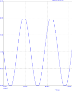
I noticed such effects long ago and applied a schottky diode between the collectors of the LTP (designing them to be on the same DC). Current at clipping through R57 and the output voltage is w/o oscillatory hooplaThe path has unlimited current capability since U10 current go through U6 emitter, with a clipping highly non linear behaviour U10 will provide as much current as it can to U6 base, at this point all the excess current will be limited only by the VAS emitter resistance, wich will be of no effect since it has very low value, remember that in clipping conditions there s no more any NFB.
In amp design all current paths must be limited such that there can be no destructive excess current if the amp enter a non linear zone, often it is not taken account of this case, that s why lots of amps experience failures on the long run while a more cautious design would make them litterally immortal.
Attachments

@wahab
U1 in the LTP can sink max 5,3 mA in worst case, but when the upper VAS stage U6 is driven into saturation via U10 by slightest current overdrive, the majority of the that current will start to pass through the Baker clamp due to U6 Vce starting to saturate, that is because it can be as low as 0,1V (see attached picture for KSA1381) meaning it can go past required Vbe to satisfy on-state conduction mode, that is, the Baker clamp will self-strangle any currents through U10-U6 because there will not be enough Vbe*2 to cause any current runaway scenario during U6 saturation.

@Aridace
Your attached circuit does not use a Baker clamp or any other current limiting circuitry so of course there is no current limiting properties around the VAS stage that could prevent rail sticking, also, a Baker clamp can not be added straight forward onto your circuit because of Q74 cascode, it would have to be reworked.
@bucks bunny
U7 is a CCS and not in any situation over-driven by any preceding gain stage causing rail sticking, so therefore does not need any Baker clamp or other current limiting circuitry
U1 in the LTP can sink max 5,3 mA in worst case, but when the upper VAS stage U6 is driven into saturation via U10 by slightest current overdrive, the majority of the that current will start to pass through the Baker clamp due to U6 Vce starting to saturate, that is because it can be as low as 0,1V (see attached picture for KSA1381) meaning it can go past required Vbe to satisfy on-state conduction mode, that is, the Baker clamp will self-strangle any currents through U10-U6 because there will not be enough Vbe*2 to cause any current runaway scenario during U6 saturation.
@Aridace
Your attached circuit does not use a Baker clamp or any other current limiting circuitry so of course there is no current limiting properties around the VAS stage that could prevent rail sticking, also, a Baker clamp can not be added straight forward onto your circuit because of Q74 cascode, it would have to be reworked.
@bucks bunny
U7 is a CCS and not in any situation over-driven by any preceding gain stage causing rail sticking, so therefore does not need any Baker clamp or other current limiting circuitry
Last edited:
U7 saturates on neg clipping when the pos VAS current drops to zero and so does collector current of U7. A well known scenario, that I saw on simulation. Btw the baker clamp is of little help, but a series base resistor does the trick.
In my simulations THD varies only slightly with output bias current and output load. So I think it is dominated by VAS distortion, maybe Early effect. I should mention that all my BJT models are from Bob Cordell.
In my simulations THD varies only slightly with output bias current and output load. So I think it is dominated by VAS distortion, maybe Early effect. I should mention that all my BJT models are from Bob Cordell.
Long ago I simmed the effect of Baker clamp on distortion and decided never to use that in an audio amp. Instead I take care that max current through VAS doesn't violate parameters and response time @ overdriving is fast enough and doesn't cause any mayhem.
The baker clamp adds a small voltage dependent capacity that contributes to high frequency distortion. Like the collector-base junctions of the VAS transistors do. Anyway this is outside my focus.
ok, but does it rail-stick, or are you using the expression "saturation" interchangeably for rail-sticking, or "over-drive", sorry I didn't follow.U7 saturates on neg clipping when the pos VAS current drops to zero and so does collector current of U7.
@Aridace
As for distortion factors, I don't disregard it, but these current limiters were introduced earlier in this thread because people were concerned with rail sticking and ability to limit the current (beginning with posts #42, #69, #72, etc..), it's understandably a trade-off for a bit higher distortion.
Usually the non-linear capacitance inside semiconductors come into play at very low voltages over them where the capacitance grows exponentially (for the BAV21 it's somewhere below 2V) meaning near full output which can't be a very pleasant listening experience, but for casual listening where the audio signal will keep the Baker clamp diode well voltage-reversed where the capacitance is not that non-linear is not of a great concern, +/-5V p-p output would cause a very small capacitance deviation of ~0,05 pF.
My wording may have been a bit misleading. The fact is that when the hi-side VAS transistor is blocking during low-side clipping, the collector current of lo-side VAS-transistor drops to zero and there is no current gain remaining. This produces a sharp rise of base current which is limited by the emitter resistor only.
I have adressed this in a previous post, a 2.2k resistance, or a little more, is needed in serial with the base of the transistors that is used as CCS for the VAS loading.
This also help the amp starting to work at a lower supply voltage when powered on.
This also help the amp starting to work at a lower supply voltage when powered on.
@Ultima Thule: True, the choice for a clamp diode was made earlier and might be a matter of priorities. Mine are minimum distortion and fast recovery from overload (in that sequence) whereas it's obvious that currents have to remain well within limits of semiconductors used. Hence I also run sims at Fin=200 KHz to verify that.

I settled for 4700uF + 22 Ohm on both pos and neg rail.The downside being if this placed on the PCB, it is a rather large component. Normally, we'd see a CRC filter used in the power supply, with the R lower at 0.1R to 0.5R.
PSRR = 92dB at 100 Hz
I added pot 10kOhm because of the RC filter on input.I totally agree and would never install a volume pot at the amplifier input.
With more than 10kOhm the rolloff is affected.
I have adressed this in a previous post, a 2.2k resistance, or a little more, is needed in serial with the base of the transistors that is used as CCS for the VAS loading.
This also help the amp starting to work at a lower supply voltage when powered on.
I will put 2.2k in the bases of CCS.I agree with wahab
Both for the LTP and the VAS
Douglas Self alsoo did this in his Blameless
As for now I will only use a BAV21 baker clamp diode to protect U10.
As there is a debate on clippping and there has been other advices.
Best is to not drive the amplifier into clipping - why should one?
As there is a debate on clippping and there has been other advices.
Best is to not drive the amplifier into clipping - why should one?
I will put 2.2k in the bases of CCS.
Both for the LTP and the VAS
Douglas Self alsoo did this in his Blameless
Not for the LTP CCS, that s counterproductive and negate partly the benefit of the resistance in serial with the VAS CCS, this resistance keep the current from flowing entirely in the base of the VAS CCS when the amp is powered on or saturated.
300uA are enough to create a 0.65V voltage drop through this resistance, to wich should be added the 0.025-0.03V for the CCS 100R emitter resistance and of course the CCS base/emitter junction, this way about 1.5V across the 6.8k resistance that feed the voltage reference diode are enough to render the LTP fully functional, that is, the LTP would work once the power supply reach +-3V.
The other benefit is in case of clipping, in this case without resistance all the current that flow through the 6.8k would be drained through the CCS base emitter junction and the LTP would stop working with unexpected consequences...
Yes, a resistance only for the VAS CCS base.
You can eventually increase the 6.8K resistance up to 10k if you respect the proportions, that is a 2.2k coupled with the existing 6.8k, or a 2k7 coupled with a 8.2k, or a 3.3k coupled with a 10k that feed the voltage reference diode, about 2mA for the last exemple is way enough in principle, you can check it in simulations.
You can eventually increase the 6.8K resistance up to 10k if you respect the proportions, that is a 2.2k coupled with the existing 6.8k, or a 2k7 coupled with a 8.2k, or a 3.3k coupled with a 10k that feed the voltage reference diode, about 2mA for the last exemple is way enough in principle, you can check it in simulations.
- Home
- Amplifiers
- Solid State
- Cello One. Good Amplifier 15 Watt with TMC and Laterals