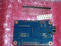
I didn't manage to have USB working. The other SPDIF/Toslink module works fine. From here
http://jlsounds.com/uploads/I2SoverUSB v.III.pdf
gpapag told me to solder only B3.
Windows recognizes device and loads driver
P.S. Transformer installed all ok
http://jlsounds.com/uploads/I2SoverUSB v.III.pdf
gpapag told me to solder only B3.
Windows recognizes device and loads driver
P.S. Transformer installed all ok
I owe you an apologygpapag told me to solder only B3.
 and a round of beers
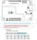
It should be "bridge B1 and B3"
George
Attachments
There is something other wrong, because it cannot open device, while the device is recognized and driver is installed. Maybe somehow I have broken it, i have gone with separate PSUs for USB and stage, so that USB ground is isolated.
@gpapag, i soldered the B1, same issue. BTW I have installed the new PSU boards almost everything SMD, they seem marvelous and stable as hell..
Today I played through SPDIF on the main system, at low-medium levels.
I managed to go upto 352 KHz with no issue.
First impressions are (as always) mixed.
I connected 0V to ground earth. Now absolute silence 🙂 (yeah!)
Now the sound, compared to SMSL D1 which is the last DAC on system (BTW Topping D90SE was replaced with a new one from audiophonics - hurray! and now i have it back, Next DAC on the system to test).
I really enjoyed voices both male and female. They seem soooo really natural.
The system is very quiet in the background. Compared to SMSL seems more smooth, more sweet but seems to lack dynamics. Stage is very good and very accurate, I believe more accurate than SMSL but not so big. Weird thing, some music seems to play better than SMSL, some other worse. Classical seems better. We seem to have a little issue with brushes, however sounds seem very natural and uncolored.
Anyway overall it is really good but I need to live some time with it to see.
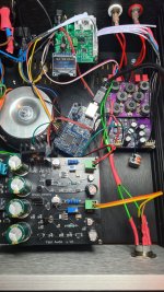
Music on the lab from USB!!! jlsounds sent me new one and works like a charm!!!
Interesting point: Plays really good on the lab!. And one more point: Abraxalito, your DAC really likes hi-res audio!
Still not put everything in place but there it is:
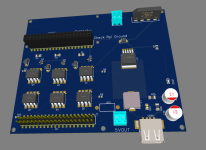
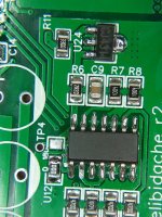
On photo I started preparing the control. It will be I2S many to many and could select more than on DACs. It will be controllable thru IR remote (ANY remote will do lol). An RPi zero will be mounted on the PCB (sorry will not be a cheap solution - if you want something cheap, China has a lot) Here is progress photo so far.
Interesting point: Plays really good on the lab!. And one more point: Abraxalito, your DAC really likes hi-res audio!
Still not put everything in place but there it is:
On photo I started preparing the control. It will be I2S many to many and could select more than on DACs. It will be controllable thru IR remote (ANY remote will do lol). An RPi zero will be mounted on the PCB (sorry will not be a cheap solution - if you want something cheap, China has a lot) Here is progress photo so far.
Attachments
Hello Richard,
I've start to build the dac but TP6 is 3V (I think is correct for the installed R15 and R16) and not 2V as indicated in the building guide.
It's ok?
Regards
Guglielmo
I've start to build the dac but TP6 is 3V (I think is correct for the installed R15 and R16) and not 2V as indicated in the building guide.
It's ok?
Regards
Guglielmo
Hi Guglielmo - you are right, its my mistake. For those resistor values TP6 should be 3V, 2V was because I changed them on the DAC I measured. On future boards I will update R15's value to give a number closer to 2V. The DAC still works fine with TP6 = 3V.
Hello,
I can change R15 also in my board to have 2V there is no problem. Would be it better?
Regards Guglielmo
I can change R15 also in my board to have 2V there is no problem. Would be it better?
Regards Guglielmo
Yes the best solution is to get TP6 closer to 2V, I use 27k for R15 which gives just a little bit below, about 1.8V. That's about the lowest which is safe.
TP6 is setting the bias voltage for the cascoding MOSFETs. Previously I'd used a FET with a higher gate threshold voltage which is why I originally had TP6 at 3V. Then I found a much lower threshold FET so was able to reduce it. But I forgot to update the build instructions to JLC which is why your board has 10k for R15.
TP6 is setting the bias voltage for the cascoding MOSFETs. Previously I'd used a FET with a higher gate threshold voltage which is why I originally had TP6 at 3V. Then I found a much lower threshold FET so was able to reduce it. But I forgot to update the build instructions to JLC which is why your board has 10k for R15.
Hello,
I've a big problem!!
The Step 1 was ok and all TP was perfect, also TP6 with a new resistor.
In the Step 2 there was 24V140mA, in the first moment go to about 170mA.
The test points are:
TP1=20,2V
TP2=11,7V
TP3=21,5V
TP4=2,5V
TP5=5,5V
TP6=2,2V
TP7=14,7V
TP8=11,8V
Do you have any suggestion?
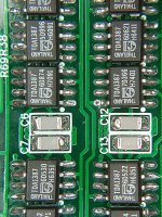
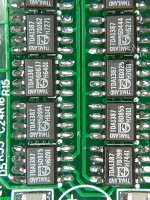
I'had some problems (I'm stupid!!) soldering the LT1028 of the left side but I don't know.
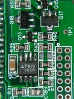
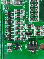
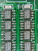
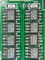
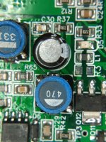
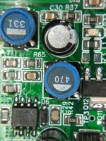
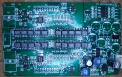
Here are some pictures of the board.
Thanks
Guglielmo
I've a big problem!!
The Step 1 was ok and all TP was perfect, also TP6 with a new resistor.
In the Step 2 there was 24V140mA, in the first moment go to about 170mA.
The test points are:
TP1=20,2V
TP2=11,7V
TP3=21,5V
TP4=2,5V
TP5=5,5V
TP6=2,2V
TP7=14,7V
TP8=11,8V
Do you have any suggestion?
I'had some problems (I'm stupid!!) soldering the LT1028 of the left side but I don't know.
Here are some pictures of the board.
Thanks
Guglielmo
Attachments
-
 20220422_235847.jpg503.4 KB · Views: 130
 -
 20220422_235855.jpg547.9 KB · Views: 132
 -
 20220422_235900.jpg639.5 KB · Views: 121
 -
 20220422_235911.jpg626.2 KB · Views: 122
 -
 20220422_235922.jpg652.5 KB · Views: 118
 -
 20220422_235931.jpg644 KB · Views: 116
 -
 20220422_235939.jpg602.9 KB · Views: 109
 -
 20220422_235951.jpg581.1 KB · Views: 109
 -
 20220423_000002.jpg495 KB · Views: 121
 -
 20220423_000008.jpg506.3 KB · Views: 114
 -
 20220423_000014.jpg505.1 KB · Views: 123
 -
 20220423_000304.jpg565.9 KB · Views: 123
Hi Guglielmo - those TP voltages you're posting have changed since step1 - the first few are too high, also there's too much current flowing. I normally get around 120mA. This suggests there is a problem around LM317 - for all the first three TPs to be too high it suggests the LM317 isn't working correctly.
Please check the voltage across R2, it should be 1.25V
Please check the voltage across R2, it should be 1.25V
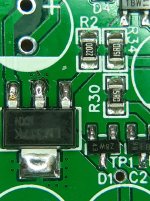
1.31V is out of spec, seems to indicate the LM317 is damaged. Normally we provide a spare in the kit, I suggest replace it.
Hello,
i replaced the LM317 but the only difference is that on R2 I have 1.254V and TP3 = 21.53V. Otherwise all TPs are unchanged, the thing that surprises me is that during Step 1 all TPs had tension as in the guide, including the TP5. Now it seems strange to me that all tensions are greater. I think the increase of the current to 140mA is only a consequence.
Any other idea?
Thanks
Guglielmo
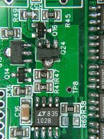
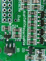
I'm really scratching my head here - there's too much current down the zener diode chain resulting in too-high TP voltages. TP2 is 1.6V too high, TP3 is too high but not 1.6V too high. So perhaps R1 has some current flowing through it, please measure the voltage across R1 (15ohm). And also measure across R35 and R36 to see what current's going into the LT1028s.
Last edited:
Now we have some progress - it seems the excess current is coming from U25. R35 voltage drop gives the game away.
What was the nature of your soldering issue with U25? I predict if you remove U25 your test point voltages will be normal again.
What was the nature of your soldering issue with U25? I predict if you remove U25 your test point voltages will be normal again.
- Home
- Vendor's Bazaar
- Celibidache NOS DAC