Thanks for that comment.The noise isn't audible as noise rather it shows up by veiling the acoustic picture painted by the system, its only really noticeable in comparison with a lower noise DAC which gives a clearer picture.
I sort of thought that, but hadn't sort of worked out that I sort of thought that.
@abraxalito Hi Richard! The box arrived and it was beautifully packaged. I soldered it all up, eventhough diyaudio.com was down and I didn't have the full rez solder guide. So I was sorta winging it. Anyways I took measurements of the test points and they all are in spec except TP 6. It is supposed to measure 2v but mine is 1.8 - not sure that is within range or not. Second issue is upon first start I got crackling that slowly went away but no music. Neither left nor right. Where should I be looking for issues?
Hans - do you have a way to check the current consumption of the DAC, it should be about 130mA with 24V supplied? Also do you have an oscilloscope that you can use to check the I2S signal is arriving OK? If not I can suggest a crude way to check that with a DMM. Those would be the first steps to debugging. TP6 at 1.8V is fine I think.
I cleaned it up and re-flowed a bunch of contacts. Now it is playing music but is extremely distorted. Seems like progress. It is super loud even at lowest volume. There is not static or noise when music is not playing, only when it is playing. Unfortunately, all I can do is DMM.
Last edited:
Does your DMM have a current range so you can check the consumption on the 24V rail? Now there is some music coming out the I2S must be functioning to some degree.
This is what I have. I don't think the current meter works, or I don't know how to use it. I don't get a reading and the DAC wont power on when I try to use it by having the current flow from the psu + through the DMM to the DAC.
Last edited:
At the 3 o'clock position it says '200mA' so it has the capability. You may need to re-plug the leads into a different socket, many meters have a different socket for amp ranges rather than volts.
@abraxalito Hey Richard, I was able to test the current draw and it is 121.1 mA. Supplied voltage is 24.
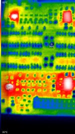
So I have double checked all solder points and there are no bridges. I have checked all TP and they are all nominal except TP6 @ 1.8v, which you said was ok. There is 6mW on the left and right output with or without the filter plugged in. The outputs are dead silent when no music is playing and is full volume crackle fest when music is playing. Here are some IR pics showing that only q4 and q2 as well as the opamps are putting out any heat at between 50-60c. In the picture opamps are on the right and q2 & q4 on the left. All other chips look fine.
I am using 3 separate power supplies. One smps300r at 28v that I am going through a buck converter down to 24v for the DAC. The USB to I2s is powered by the PC. Headphone amp is another wall wart. I tested the DAC apart from the headphone amp, just straight headphones to output and same result - total silence unless music is playing.
I am using 3 separate power supplies. One smps300r at 28v that I am going through a buck converter down to 24v for the DAC. The USB to I2s is powered by the PC. Headphone amp is another wall wart. I tested the DAC apart from the headphone amp, just straight headphones to output and same result - total silence unless music is playing.
Attachments
Supply current seems fine. '6mW' do you mean 6mV DC offset? My suspicion - based on the fact that at first you got nothing but after resoldering you got distorted sound - is that there's something amiss around the I2S input circuitry. Which 'bunch of contacts' did you resolder initially, when the DAC was silent? When fault finding the most likely fault is just a 'single point failure' which can account for the evidence. Given that it seems you get distortion out of both channels its unlikely to be the analog circuitry, which is separated into L and R channels. So we'd need two faults in the analog circuits to account for what you hear, but the I2S is where the L and R signals are combined, using the same connections.
The I2S circuitry is bottom left on the PCB, near to the I2S connector. It includes six (lower and left) of the resistors around the IC, the 74HC86 IC and U12 the phase setting 0R.
As regards the PSUs you're using, I doubt they're contributing to the fault but they're less than ideal for getting good SQ. Buck regs put out a lot of switching hash (normal mode noise) and feeding that from a switching supply means you'll get common mode noise too.
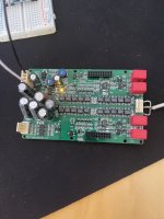
In these 2 pictures you can see the solder bridge on one of the chips. That has been cleaned up. On the other picture you can see that chip looks like a mess. On the bottom right and top left were suspected solder bridges but in the middle top is some solder paste residue. I have since cleaned up the soldering and took a tooth brush and isopropyl alcohol to the whole board to get rid of any residual solder paste and all that flux. Once I did all that, I did get music but also full volume distortion. Do you think that i2s chip is damaged somehow? Ignore how crazy the caps look. I didn’t seat the fully since once I get it running I will be playing around with those. There is also a full board pick in case something jumps out at you.
Attachments
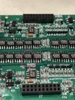

There are some suspect solder joins in the first picture, i.e. C6, C7, C12 & C13, and it looks like there is a solder bridge between pins 10 & 11 of the IC in the second picture.
Good idea Hans to share pics, from your 2nd one I have found something that may well be a major contributor to your issue. U12 (the three pad resistor footprint adjacent to the 74HC86) needs a 0R 0805 fitted, the default is between the left pair of pads. We show this by making the left two pads pinky purple in the stuffing guide. Without this resistor the I2S Data line is undefined and so it could easily be the cause of your full-volume distortion.
So after fitting the 0R on U12, it plays perfectly. Thank you. Now I need to listen to it for a while and let it burn in. It does sound quite a bit different from the phidac quad.

@abraxalito I wanted to PM you, but for some reason my account has limited rights even though it's quite old. I'm having some issues with Celibdache #1. I'm getting white noise after a minute or two of use with a thx 789. Turning the amp on and off resolves this. The amp works fine with other dacs. I suppose it could have something to do with the output, ground of the left and right channel, of the Celibdache not going to the chassis/earth ground at all. The THX 789 is not grounded by default either. I did not have this issue with a bottlehead crack headphone amp that was grounded to earth ground. Any idea where to start to diagnose/fix this?
White noise which stops after power cycling the amp? Sounds more likely to be a problem on the digital side than analog. Is the white noise very loud or just low-level? Both channels?
Does the white noise only happen with THX789 as amp? I would definitely recommend a ground lift resistor (10ohm) between Celi circuit 0V and mains earth but I've not had a grounding issue give rise to white noise, its usually hum that's the symptom. The music cutting out entirely would also indicate an issue on the digital input rather than the output, if its an output grounding issue the music would still be there even if swallowed up by noise.
As always, I only understand half of what you're saying... entirely my fault 🤣 A ground lift resistor would be a 10 ohm resistor from the chassis ground to 0V on the Celibdache...but I don't know where that via is on it 🤣 Does the power handling of the resistor matter? The digital input board now that I think about it is also not grounded at all.
Power handling of the resistor? Strictly speaking to handle a ground fault current it would need to be rather large but putting that to one side a 0.5W one would normally be fine. The output 4 pin connector has two 0V pins, you could use one of those as one terminal of the resistor if your RCA outputs can cope with just one 0V wire to the DAC.
- Home
- Vendor's Bazaar
- Celibidache NOS DAC