Reading TOC on new discs?
Peter Daniel wrote:
'I also dealt with the problem of changing discs and getting new TOC each time. I connected a switch to a lid output and instead of using STBY button and clicking twice as well as disconnecting power each time, I click only once and have a new TOC for ea. disc in a more proper way."
Peter, to implement this function using the lid switch did you just connect a switch across the J2 connector on the display to read the TOC on the new disc or is there more to it?
Thanks
Tim
Rarkov said:More pics please! Looks great. Where is the schematic from, Rod Elliott?
Thanks,
Gaz
Hi,
the power supply is totally ordinary with a regulator (LT317AT) and adjustable resistance i the circuit to get correct voltage level. As boards I ordered two Wellmann kits as this is the cheapest way for me. The circuit resemblances of the UPS scetches for simple power supplygiven by Nico Thevissen NL.
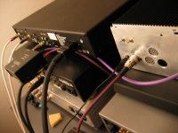
PS! I got rid of the slightly edgy treble by re-soldering the digital cable connections - jitter is sure an unpredictable matter!
Attachments
BrianGT said:Here is the bottom of another philips transport, used in the Mark Levinson 31.5:
--
Brian
The module call CDM12 industrial,
Using CDM12i OPU metal unit with TDA1302 Laser Pre-Amp IC.
On board IC CHIPSET LIST:
SAA7345GP - CD6:digital servo DSP
OQ8868 ? - CD digital servo IC
TDA1301 - CD servo amplifier
TDA7073x2 - Servo driver
80C32 - MCU unit /DSA IF control
Notice : the board using external CLOCK.(Oscillator already remove)
Re: Reading TOC on new discs?
AFAIR this is it. Just a momentary switch on dispaly board, where the wires would go to a lid switch, works well.
TimSr said:Peter Daniel wrote:
'I also dealt with the problem of changing discs and getting new TOC each time. I connected a switch to a lid output and instead of using STBY button and clicking twice as well as disconnecting power each time, I click only once and have a new TOC for ea. disc in a more proper way."
Peter, to implement this function using the lid switch did you just connect a switch across the J2 connector on the display to read the TOC on the new disc or is there more to it?
AFAIR this is it. Just a momentary switch on dispaly board, where the wires would go to a lid switch, works well.
Upgraded my PSU
Hi,
When I first build my CDPRO2 player I have used a PSU with uA 7805 / 7809 regulators. I recently replaced this PSU by a design with LM 317 (1 x 5VDC, 1 x 9VDC and 1 x 5VDC).
I have the strong feeling that this PSU sounds better. I use the I2S output with a TDA 1543 Non-os dac.
With this PSU the sound is more detailed, more "black" between the instruments and is "quicker".
Since I use the I2S output on the CDPRO and did not change anything in the (external) DAC I wonder where this difference comes from.
I would appreciate it if somebody can clarify this a little.
Best regards,
Peter
Attachments
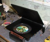
Well I have finally thrown my hat in the ring, here is the beginnings of my CDPRO Chassis. The drive will eventaully be located inside the Acrylic with TOP access under a flip up lid. The face plate is not on yet. I am experimenting with sand blasting the Acrylic to make it translucent. Then I will mount several LED's so the block will glow the color of the LED's. I may even use tricolor LEDs' and have it cycle through different colors. I am experimenting with a scrap peice first.
More photos at:
Anthony
An externally hosted image should be here but it was not working when we last tested it.
An externally hosted image should be here but it was not working when we last tested it.
More photos at:
An externally hosted image should be here but it was not working when we last tested it.
Anthony
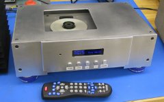
I decided to make another CD-Pro based transport and this is what I'm starting with. The original lid from ML31.5
http://www.marklevinson.com/image_library/index.asp?categoryID=1&productID=15
I bought it for $100 😉
http://www.marklevinson.com/image_library/index.asp?categoryID=1&productID=15
I bought it for $100 😉
Attachments
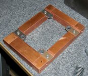
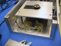
The transport is mounted in a copper frame, made out of 1" bar. I put it together using #10 screws. Original design from Madrigal is using lead, but I prefer to work with copper. It's quite heavy and sturdy, no need to milling it out of one piece (it would be too expensive). Frame will be additionaly mounted on 4 springs.
Attachments


Peter did you use a Dado blade to cut the notch out. Are you still using that Freud Non-Ferrous Metal Blade hows it holding up.
I just hate getting metal shaving in my cabinet saw and the dust collector does not do a good job on metal. It was bad enough cleaning aluminum for my bandsaw and all the DW40. Also, due you use a lube when cutting table saw.
I just hate getting metal shaving in my cabinet saw and the dust collector does not do a good job on metal. It was bad enough cleaning aluminum for my bandsaw and all the DW40. Also, due you use a lube when cutting table saw.
I didn't use Dado blade as the one I have is not specified for metal. I used my Freud blade and just made numerous cuts (in two depths: 0.1 first, 0.2 final depth). I thought saw cuts would be enough, bet eventually decided to shave it to nice surface with 1/2 straight router bit. It worked fine and the finish is like from professinal milling machine.
I was initially also reluctant to use my table saw for cutting metal, but I'm using wooden guides and I place a piece of MDF on a table's surface, so no damage yet.
I'm not using any lubricant for cutting.
I was initially also reluctant to use my table saw for cutting metal, but I'm using wooden guides and I place a piece of MDF on a table's surface, so no damage yet.
I'm not using any lubricant for cutting.
Peter,
I was told by local shop that the router would work but I"ve been to chicken. If I use my router table there are chances the metal shaving will fall into the router's motor. Did you use a carbide sprial fluted bit.
Yea, a piece of MDF over the top of the table saw sound like a good idea. I'll try that.
Thanks
I'm using mostly this bit with metals and plastics (1/2 or 1"). To avoid metal shavings fall into router (I think that air movement prevents this already) I use 1/4" hard board over the table, with the hole made by router bit. This also prevents the metal ring (reducing the hole in the router table) from falling out. It happened to me once and it was a mess. It's good to use tape to attach it more securely. I always shave only a tiny bit of metal with a router as anything more may be too dangerous. All the rough work is done with a saw.
Attachments
Here is the latest picture of my project. It was done for my school project, and I got checked off for it today. I will continue to work on it on my own.
Left to do:
-add plexiglass sliding door, and blue leds
-anodize chassis, thinking front middle part black, rest clear
-add i/v stage to tda1541a dac (finish the pcb that I am working on for it) [currently just a 100 ohm i/v resistor]
-get the new control pcb made, and replace the larger prototype board
--
Brian
Attachments
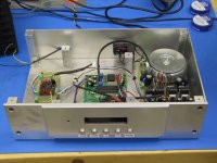
Here is one more picture, showing the arrangement of the insides without the transport. I have more pictures of the earlier development of the project here:
http://www.diyaudio.com/forums/showthread.php?s=&threadid=21475&highlight=
Once I get the new control pcb made, it is designed to fit on the back of the Optrex 20x2 lcd that is used in the DipChip kits. This should simplify the internal wiring a bit.
The power supply uses LT1085 regulators, with a CLC setup on the cdpro2 lines, along with plenty of capacitance.
--
Brian
Attachments
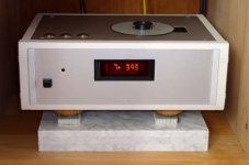
Hey Brian,
That looks great! I like the way u mounted the cd-pro2 drive. How does it sound?
I`m hoping to complete mine next month. I will use a marble block/plate on which I will mount the cd-pro2, but the way u mounted it, is also very cool.
If u have any more pictures, post them!
That looks great! I like the way u mounted the cd-pro2 drive. How does it sound?
I`m hoping to complete mine next month. I will use a marble block/plate on which I will mount the cd-pro2, but the way u mounted it, is also very cool.
If u have any more pictures, post them!
- Status
- Not open for further replies.
- Home
- Source & Line
- Digital Source
- CD PRO 2 - The making of a high end CD Transport