Peter: when you built the 1541 and 1543 dacs, was it on a veroboard or did you make a pcb?
I'm on the way to build one, and I'm wondering if it would be worth the work to make a pcb
I'm on the way to build one, and I'm wondering if it would be worth the work to make a pcb
in this case SPDIF sounds better to me than I2S
it isn't because of the interface that you prefer the outboard dac....i'm shure you build a very fine dac with tda1543 chips....

Peter Daniel said:1543 was veroboard (p2p), 1541 was PCB inside Marantz player (original).
since you're always comparing many things like resistors, caps, wires, chassis materials...
have you ever tried veroboard vs. pcb?
Re: Re: Right on Target
Hi Peter,
I believe you do compare apples with peares a bit.
You have TDA1541 inside a player (I2S) and TDA1543 in a separate DAC with SPDIF.
I simply connected my TDA1543 to the decoder in the Philips CD-650 or through the SPDIF using CS8412/Wildmonkeysects PLL filter/ low noise analog supply for the PLL. Comparing both, the direct I2S connnection using four wires: DATA, BCK, WS and ground was more smooth, less audible distortion.
What puzzles me is when I place the TDA1543 inside the player sound is definetely worse.
Kal Rubinson wrote two interesting articles about direct I2S connection in the Audio Amateur1995 & 1997. Backissues available from www.audioxpress.com
😎
Troels, Carefull with the booze
Peter Daniel said:
Well, this is not that simple, I would say. Proper implementation of everything else is equally important. I have modified Marantz CD-94 in non-oversampling mode with 1541 DAC connected with I2S inside the player.
I still prefer Marantz as a transport feeding a separate DAC based on TDA1543 using SPDIF. It is true that separate DAC is using better supplies and reclocking and passive output, while TDA1541 doesn't have all that and the output is done with OPA627. But in this case SPDIF sounds better to me than I2S.
Hi Peter,
I believe you do compare apples with peares a bit.
You have TDA1541 inside a player (I2S) and TDA1543 in a separate DAC with SPDIF.
I simply connected my TDA1543 to the decoder in the Philips CD-650 or through the SPDIF using CS8412/Wildmonkeysects PLL filter/ low noise analog supply for the PLL. Comparing both, the direct I2S connnection using four wires: DATA, BCK, WS and ground was more smooth, less audible distortion.
What puzzles me is when I place the TDA1543 inside the player sound is definetely worse.
Kal Rubinson wrote two interesting articles about direct I2S connection in the Audio Amateur1995 & 1997. Backissues available from www.audioxpress.com
😎
Troels, Carefull with the booze
My latest experience with this issue have been a drive and a DAC from the italian manufacturer Northstar:
Drive
DAC
Both machines feature S/PDif as well as an I²S-Link.
Although there is a lot of up- and oversampling going on, I woul call the sonic differences between the interfaces dramatic.
The I²S link plays much easier, faster, with more resolution and a tighter bottom end.
Drive
DAC
Both machines feature S/PDif as well as an I²S-Link.
Although there is a lot of up- and oversampling going on, I woul call the sonic differences between the interfaces dramatic.
The I²S link plays much easier, faster, with more resolution and a tighter bottom end.

Beautiful work GeirTj!
Well done. I hope it you enjoy it as much as we enjoy looking at it! More pics?
Thanks,
Gaz
Well done. I hope it you enjoy it as much as we enjoy looking at it! More pics?
Thanks,
Gaz
Rarkov said:Beautiful work GeirTj!
Well done. I hope it you enjoy it as much as we enjoy looking at it! More pics?
Thanks,
Gaz
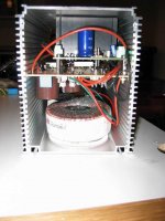
Thank you Rarkov!
It’s all built up of three relatively cheap data card (?) boxes where vero-boards fit exactly. I would however not recommend the use of such extruded boxes where only the end lids can be removed as the running of wires etc becomes rather cumbersome. The boxes are all mounted on a damping platform which shall cancel vibrations (by a so-called counter weight middle plan). Oh yes – I do enjoy the sound now from the machine 🙂 I’m way below the level of know-how the guys show on these pages, but it seems that a jitter-reducing oldie (Theta Time Linque Conditioner?) on the path from transport to my external Electrocompaniet DAC has removed some symptoms and I now have a broad smile on my face.

Member
Joined 2002
I might be headstrong pursuing this topic: Is not the SPDIF and AES/EBU variations of the same “coding” only differing in the way that the SPDIF has a 0,5 V differential potential and is not balanced versus the AES/EBU having 5 V differential potential and is balanced? I’ve ordered a Sowter model 8285 transformer (http://www.sowter.co.uk) to decouple the SPDIF signal path and produce a balanced signal. By these simple means I do not achieve a 5 V differential potential though, but I’m curious to see how sensitive the external DACs AES interface is to these voltage levels. GeirTj
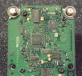
BrianGT said:Here is a picture of part of the circuit board:
--
Brian
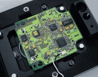
could we have a closer picture? to be able to read what's on the chips 😉
Thanks for these pictures.
I would be interested to see how mechanics look.Especialy motors,laser ...and all mechanic parts that are probably visible when the board is taken off.
Bartek
I would be interested to see how mechanics look.Especialy motors,laser ...and all mechanic parts that are probably visible when the board is taken off.
Bartek
Bricolo said:
could we have a closer picture? to be able to read what's on the chips 😉
The main chips are listed on the Daisy page:
http://www.daisy-laser.nl/homeoptics/page9.html
They have the user manual, and the datasheets for the ICs on the circuit board.
--
Brian
It seems that it is possible to use a (Sowter) transformer to "konvert" a 0,5 V unbalanced S/PDIF signal and make it readable for a balanced 5 V AES input on a DAC (though still having a potential of 0,5V). There was a slight sonic degrading compared to S/PDIF the-whole-way approach, so in one way - an useless exercise.
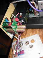
Have built a rechargeable battery powered supply for the CD-PRO2's 5V signal circuits plus battery powered supply for a Theta jitter reduction box. The sound got definitely more resolved compared to mains supply of both but Ive also got a slight stingy treble that I'm not absolutely confident with. Ill make the whole switchable between the two power supply modes to make A-B comparison easy. I attach a photo of the very simple (and cheap) battery supply.
geirTj
Attachments
- Status
- Not open for further replies.
- Home
- Source & Line
- Digital Source
- CD PRO 2 - The making of a high end CD Transport