Congrats for the great cdp Peter ! I do have one question regarding this kit. i see you built a separate tower for the DAC, what does it mean. You want to use a different DAC than the default one ? Or there is no DAC in the kit so the only output is digital ?
There was a DAC on CD-PRo board, but obviously, quality wasn't the best. I decided to go with a different arrangement (non-oversampling) and use separate DAC, but inside a player. Currently I tested TDA1543 and TDA1541, I still have one more left, which is AD1865K. The second tower is only for a PS, the DAC will be on a same platform as a transport.
Ah so the dac chip is located on the PCB attached under the mechanism; i see now. How bad would this default DAC is. Considering the kit is lets say 500 euros, does it sound at least like a commercial 500 euro cdp lets say from Marantz. I dont have the skill or the cash to start trying other DACS, but the DIY ideea is too attarctive. I just finished a pair of loudspeaker and right now working on a Leach Amp.
On the cover I was thinking at something like a turntable has, ie a very thick glass lid which would fit perfectly between your towers.
On the cover I was thinking at something like a turntable has, ie a very thick glass lid which would fit perfectly between your towers.
Hi,
I have just started my PCB and whilst drawing it up, noticed something. I am not convinced it'd work "as advertised!". The PSU is the one here... A simple but yet effective supply suggestion. My value for Rx was calculated at 187.6Ohms and I am using 188Ohms. My problem in understanding this is that if the total peak to peak of the transformer is 24V (2x9V secondaries) and you tie the positive side to ground, how can a resistor in series mean the output is -22.5V?! Furthermore, what is this voltage with reference to - it certainly can't be GND! Please explain to me how this works - even my spice simulator is getting confused!
Thanks,
Gaz
Rarkov,
The PSU as drawn on the Daisy webside works, the value that you calculated is oke. I have the same situation here, however I have noticed that the series resistor is getting really hot. I am using approx. 20 pcs. 0,25W resistors in a parallel/series combination that makes together approx. 180Ohm and it still heats the complete (12 kg) housing.
After I come back from my holidays I will change my PSU to the the PSU that is on the webside of A. Galavotti.(http://www.geocities.com/agalavotti/cdpro.htm)
Best regards,
Peter K
Hi Peter,
I'm using two 10W resistors in series (120R and 68R). So what are the -22.5V and -24V in reference to? Ground? If it is ground then I do not understand the schematic at all!
Thanks,
Gaz
I'm using two 10W resistors in series (120R and 68R). So what are the -22.5V and -24V in reference to? Ground? If it is ground then I do not understand the schematic at all!
Thanks,
Gaz
Rarkov said:So what are the -22.5V and -24V in reference to? Ground? If it is ground then I do not understand the schematic at all!
If you are talking about display PS, don't worry, I had some problems with understanding it the beginning too. I don't remember it now, but if you use webside of A. Galavotti and copy the supply exactly, it will work.
Rarkov said:Please explain to me how this works - even my spice simulator is getting confused!
I am sure you understand how it works otherwise you wouldn't know that you need approx. 180 Ohm.
The voltagedrop over Rx is 0.125 * 180 = 22.5V. When the positive side of the bridge is connected to GND (which it is in my CDPRO) the voltage that you measure on Vff is compaired to GND -22.5V, Vfk is Utotal-22.5V = approx 2,5 V.
In my experiences this part of PSU is not that critical.
Peter K.
The power flow is explained here:
http://www.daisy-laser.nl/homeoptics/page13.html
You have the positive voltages +5 and +9 V referenced to GND, and you need something like -20 (+-2) V referenced to GND. There is only a little current from GND to this -20V.
Than you need about 2,5 V more negative than the -20, there should flow about 125mA for the heating of the display tube from -20 to this -22,5V. If this current is to much the display will give up displaing anything early. If its less it will be darker but live will be longer.
So it is important Vff is around -20V to ground, and Vkk so much lower that there is this ~125mA flow.
I use a series resistor of around 180R 3W and glued a little heatsink on it because it is really hot, but works without problem.
Ah-ha! Got it!
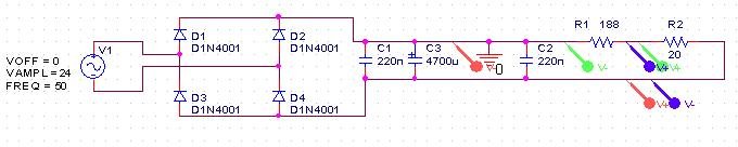
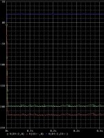
I forgot to add the 20 Ohms for the display - so the values were either at ground or at -24V. Here is the schematic as I have simulated it...I used differential probes to make sure I got it right - just in case. It is suggesting that -Vff is at 20V and -Vkk is at 22V. The voltage difference is a very constant 2V dispite a noisy line...Here are the pics...
Thanks so much for all your help!
Gaz
Attachments
Rarkov,
can you please inform me what software tool you are use for simulation.
Thanks,
Peter K.
can you please inform me what software tool you are use for simulation.
Thanks,
Peter K.
Hi Rarkov,
Thanks for the info and your offer, but orcad isn´t shareware isn´t it? Or do you mean the output files?
Anyway I am going to beautifull and hot Italy tomorrow, lets come on this in a couple of weeks.
Best regards,
Peter K
Thanks for the info and your offer, but orcad isn´t shareware isn´t it? Or do you mean the output files?
Anyway I am going to beautifull and hot Italy tomorrow, lets come on this in a couple of weeks.
Best regards,
Peter K
Pics of my CD-PRO2 PSU and TDA1543 DAC / PSU are here...
http://www.diyaudio.com/forums/showthread.php?postid=208535#post208535
Enjoy!
Gaz
http://www.diyaudio.com/forums/showthread.php?postid=208535#post208535
Enjoy!
Gaz
Can someone help me with a CD-PRO2 PSU question?
My PSU is putting out -28.4V for -Vkk (or -26.8V with a string of 6 Series resistors) Where as it should be -24V...
The voltage over the filament heater is 3V where as it should be 2.5V.
Would I get away with these voltages? I have forgotten to check the value of -Vff which should be around -22.5V.
Maybe I should just get a new 7V secondary transformer instead of the 9V I'm using.
TIA
Gaz
Sorry - I wasn't with it went I wrote my last post...I meant 6 series diodes!
My mistake - sorry!
Thanks anyway,
Gaz
My mistake - sorry!
Thanks anyway,
Gaz
Hiya,
Just an update...
When I was testing the diode idea, I had replaced the fuse with 6 series diodes. However, this made little difference. I have realised that this is my error (the fuse is for only one line and does not effect both -Vff and -Vkk so it didn't help. The reason I did this was so I didn't have to take my circuit apart.
In the end, I bit the bullet and cut the +ve track off the bridge rectifier. I wired my series diodes in on the copper side of the board and it looks fab (in fact you can't see a difference from the top! 😉 I will put pics on the other thread tomorrow) The circuit is now outputing 2.70V and 24.8V so all that's left to do is find space for one more diode. That'll bring it down perfectly cause at the moment I'm testing with 23.5R (47R // 47R) and when you lower the resistance (to the actual 20R max.), the voltage rises. That will be outside the 10% (2.75V) limit for the heater. Also - even though my multimeter is new today, it is not calibrated - so I wouldn't like to test it!
Thanks,
Gaz
Member
Joined 2002
- Status
- Not open for further replies.
- Home
- Source & Line
- Digital Source
- CD PRO 2 - The making of a high end CD Transport