I will tomorrow...It's 4am here and I'm really not feeling too good...7 hours after a meal out - coincidence?! Either way I'm not moving! 😉
Member
Joined 2002
Hiya,
New pics of diode mod and new multimeter start at this post...
http://www.diyaudio.com/forums/showthread.php?postid=209101#post209101
Enjoy...
Gaz
New pics of diode mod and new multimeter start at this post...
http://www.diyaudio.com/forums/showthread.php?postid=209101#post209101
Enjoy...
Gaz
Hey, Peter, congratulations for your CDpro!
I'm reading about this mechanism since it was allowed by Mr. Thevissen. But as I'm in Loudspeaker DIY matter and several other expensive hobbies, I had never spent time to buy or assemble it. My DAC today is a project based on something like EVM-1702(B-B), but custom PCB. As several people are getting success with the CDPRO, I'm planning to try one also. I hope you don't matter if my enclosure gets similar to yours... really GOOD ideas.
One more time: congratulations!
Hisatugo.
Right! This is P***ing me off! I got my new CD-PRO2 working and it's great - and that's with no effort (using analogue outputs & no shielding).
The problem is this: When I received the unit, the display has what can only be described as a "molten burn mark" in the bottm right hand corner. This is about 8mm in diameter. Is this normal for VFDs? Anyway - I connect up the PSU and it wont work! I realise that my circuit is wrong but I figured that if I connect it as labeled, it should work...Can someone take a look and see if they can see a problem?
Doing a major rechange on the PSU is out of the Question ATM. How long does it take to power up the display?!
Thanks,
Gaz
Attachments

Hi Gaz,
I can not remember a "molden burn mark" on my display PCB, I suppose it is not there in my case.
Looking at your diagram things look fine to me. Did you connect ground (PIN 1 of Jumper 6) to the displays ground?
Good luck,
Peter K.
I can not remember a "molden burn mark" on my display PCB, I suppose it is not there in my case.
Looking at your diagram things look fine to me. Did you connect ground (PIN 1 of Jumper 6) to the displays ground?
Good luck,
Peter K.
Peter K said:Looking at your diagram things look fine to me. Did you connect ground (PIN 1 of Jumper 6) to the displays ground?
Hi,
Thanks for the quick reply. According to this page - Click Here - you are talking about tying the ACK pin to ground?
Are you sure?
HBarske:
That makes me feel better - thanks. Now just to get it switched on!
Thanks,
Gaz
Rarkov said:Ah-ha! Got it!
I forgot to add the 20 Ohms for the display - so the values were either at ground or at -24V. Here is the schematic as I have simulated it...I used differential probes to make sure I got it right - just in case. It is suggesting that -Vff is at 20V and -Vkk is at 22V. The voltage difference is a very constant 2V dispite a noisy line...Here are the pics...
Thanks so much for all your help!
Gaz
Hi,
Usually fuses and series resistors aren't connected in ground PS line. Here, must be inserted in -24V rail. IMHO
Regards
I admit - I don't understand the circuit at all, but that is one of the circuits posted on the Homeoptics website.
Nico has written to me confirming that it is certainly OK to have that mark there. It is only a problem if it turns into a white ash and the numbers go brown.
Any ideas for getting this thing working. What is this GND and Display GND that need tying as Peter K mentioned?
Thanks,
Gaz
Nico has written to me confirming that it is certainly OK to have that mark there. It is only a problem if it turns into a white ash and the numbers go brown.
Any ideas for getting this thing working. What is this GND and Display GND that need tying as Peter K mentioned?
Thanks,
Gaz
Rarkov said:
Gaz,
No not the ACK pin!
With "Jumper 6 Pin 1" I mean the JP6 as mentioned in your diagram.
To let the system work you need to connect (IMHO) the ground (in your diagram between C12 and C13 = JP6 Pin1) to the PCB ground (J1 Pin 4 on the display PCB).
BTW: When switching on the power the display does not need "any" time to start-up, it will work directly.
Peter K.
Ah, sorry - got my wires crossed! (pun intended!)
I'll give that a go when I get home from work.
Thanks,
Gaz
I'll give that a go when I get home from work.
Thanks,
Gaz
Interface with external DAC
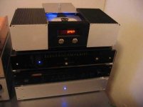
I’ve very recently completed my CD-PRO2 which I initially intended to use as a transport only in conjunction with an Electrocompaniet EMC1 24/192kHz upsampler/DAC. What puzzles me is that the CD-PRO2 sounds better in my system through its own DAC. I suspect that the connection between the transport and the external DAC is introducing jitter or in other ways is not engineered properly by me. On the CD-PRO2 board I’ve connected to the AES/EBU by soldering directly to the tiny pins approximately 10 cm twisted silver leads. These are again soldered directly to the end of a 0,5 meter 75 Ohms quality digital cable that is finally connected to the external DACs RCA plug for SP/DIF (assuming that AES/EBU and S/PDIF are equivalent(?)).
A possibility is that the CD_PRO2 internal DAC is that good overshadowing the Electrocompaniet DAC but considering the very positive response this DAC has received world-wide, I’m eager to ensure that the DAC has fair working conditions. Besides, it has balanced output which suits well with the rest of the gear. I hope someone has some thoughts on the interface matter.
Attachments
assuming that AES/EBU and S/PDIF are equivalent
they are not.....
the digital interface between the transport and the outboard dac is one of the biggest problems in the world of cd playback.
there has been written alot about it in this forum - use the searchbutton......
tbla said:
they are not.....
the digital interface between the transport and the outboard dac is one of the biggest problems in the world of cd playback.
there has been written alot about it in this forum - use the searchbutton......
Hmm,
I just wondered if anyone have specifically resolved the CD-PRO2 to external DAC interface issue. Though the CD-PRO2 has the wording EBU as notation on the board pins, it gives out a 0,5 V signal which seems to comply with the SPDIF potential - and I do get reasonably good sound quality out of the external DAC though the DAC denotes the 75 Ohm 0,5 V RCA input as "SPDIF".
GeirTj 🙂
I'd think the question why the internal DAC sounds better is rather simple to answer: It is connected via I2S, wich is way better then any S/PDif-interface.
Right on Target
Right and right! SPDIF worsens sound.....

Hi Holger,HBarske said:I'd think the question why the internal DAC sounds better is rather simple to answer: It is connected via I2S, wich is way better then any S/PDif-interface.
Right and right! SPDIF worsens sound.....


Re: Right on Target
Well, this is not that simple, I would say. Proper implementation of everything else is equally important. I have modified Marantz CD-94 in non-oversampling mode with 1541 DAC connected with I2S inside the player.
I still prefer Marantz as a transport feeding a separate DAC based on TDA1543 using SPDIF. It is true that separate DAC is using better supplies and reclocking and passive output, while TDA1541 doesn't have all that and the output is done with OPA627. But in this case SPDIF sounds better to me than I2S.
Elso Kwak said:
Hi Holger,
Right and right! SPDIF worsens sound.....
Well, this is not that simple, I would say. Proper implementation of everything else is equally important. I have modified Marantz CD-94 in non-oversampling mode with 1541 DAC connected with I2S inside the player.
I still prefer Marantz as a transport feeding a separate DAC based on TDA1543 using SPDIF. It is true that separate DAC is using better supplies and reclocking and passive output, while TDA1541 doesn't have all that and the output is done with OPA627. But in this case SPDIF sounds better to me than I2S.
- Status
- Not open for further replies.
- Home
- Source & Line
- Digital Source
- CD PRO 2 - The making of a high end CD Transport