okay, I am going to be honest, looking at the chip, do I need to use a general ground point or is there one on the chip?
you maybe laughing and cringing at the same time, but I have never done this before, i know that there will be a gnd on the chip, should I use that?
you maybe laughing and cringing at the same time, but I have never done this before, i know that there will be a gnd on the chip, should I use that?
it also looks like a CD582 from philips, now I am more knowledgeable they look more similar, in relation to the chips layout anyway.
Apologies for pointing you in any wrong direction.
Apologies for pointing you in any wrong direction.
Unless there were some obvious problem you can spot, I think the possibility of a faulty chip has to be considered.
But don't be under any illusions about an easy fix... I didn't think this would have gone this far tbh.
All you can realistically do (and this applies to any faulty equipment) is to check ALL the supplies are correct... and if you haven't a correct circuit then that means pulling the data sheets for all the IC's and seeing where the supplies are.
If it were me, I would consider the RAM suspect.
These are available,
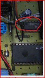
Semiconductor: MN4264-15 (MN 4264-15) - 482220970422 IC PHILIPS...
or try and get a scrapper of ebay that uses the same chip set, then you have the SAA IC's too.
But don't be under any illusions about an easy fix... I didn't think this would have gone this far tbh.
All you can realistically do (and this applies to any faulty equipment) is to check ALL the supplies are correct... and if you haven't a correct circuit then that means pulling the data sheets for all the IC's and seeing where the supplies are.
If it were me, I would consider the RAM suspect.
These are available,
Semiconductor: MN4264-15 (MN 4264-15) - 482220970422 IC PHILIPS...
or try and get a scrapper of ebay that uses the same chip set, then you have the SAA IC's too.
I'll have to leave it for today... don't get your hopes up too much... the last thing I want is you to pour money into it and still not fix it.
The players an unknown... I'm guessing you don't know it's history, whether it's ever been worked on before etc... don't be under any illusions.
The SAA7310 chips are hard to come by and dear at around £50
http://www.chsinteractive.co.uk/electrical-components/misc/i-c-saa7310-philips.htm
Much better to get a donor machine. I think some Rotels used a similar chip set... the Philips based machines were used by many.
Okay the DRAM is fine at 5.1volts on pin 9.
I tested the SAA and I am not sure that I am doing it 100% so want to run through and check:
1. negative lead on GND on the machine (same one I used testing the DRAM chip)
2. The positive lead on pin 5 and then on pin 28 separately
Is that correct?
If it is correct then I am getting weird readings on this chip (certainly not -5v)
pin 28 is giving 10mV
pin 5 is giving 620mV
I think that I am doing something wrong, help!!
okay its not the CD630 as this chip is the SAA7310 a 44 pin chip, mine is definately more like the CD582 which has the SAA7210 but the block diagram is not so comprehensive or is that me reading it wrong?
Last edited:
found the pin layout for my SAA7210 in my player, am I simply checking the supply voltage to it, and would that be pin 40?
wasnt sure what you meant by the -5v
SAA7210 Datasheet pdf - Decoder for compact disc digital audio system - Philips
wasnt sure what you meant by the -5v
SAA7210 Datasheet pdf - Decoder for compact disc digital audio system - Philips
well, determined I am, I have checked pin 40 on the SAA7210 chip, it reads 5v, me thinks its okay, what do you think?
Going to order that chip and see what happens, as its only cheap.
Going to order that chip and see what happens, as its only cheap.
This is getting confusing.
Supply on the RAM is OK... this IC is still favourite at the moment.
Your piccy shows an SAA7220. Supply here is pin 24 at 5volts, pin 12 as ground.
If the other chip is an SAA7210 then 5 volts on pin 40, ground on pin 20.
What's on pin 21 out of interest ?
I'm sure these will be OK... and I think the RAM would be favourite to to swap... but remember no guarantees.
Definitely worth looking through some Rotel manuals and seeing if same chipset used... they must crop up on ebay.
hi, pin 21 shows -2.5v which seems right according to the datasheet.
Although no guarantees I am with you on trying the chip, as its not too much, and not 40 pins of soldering, argghh, only 18pins.
I will feedback as soon as I have tested. Have a great day.
Although no guarantees I am with you on trying the chip, as its not too much, and not 40 pins of soldering, argghh, only 18pins.
I will feedback as soon as I have tested. Have a great day.
- Status
- Not open for further replies.
- Home
- Source & Line
- Digital Source
- CD player with distortion. laser?