the closest that I can find is the CD630 although not 100% that its the correct one, only that it uses the right transport and dac circuit layout looks very similar.
Does it give the laser and front end circuits ? Philips sometimes have those as a separate manual.
Have you found the procedure in the manual ? what does it say to do.
Sometimes Philips methods are convoluted requiring resistor networks etc to be added.
Is it "one of those" ?
Think it is one of those

Does it give the laser and front end circuits ? Philips sometimes have those as a separate manual.
it shows the servo and decoding panel?
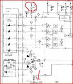
If it's the same as the CD630 then you play a good CD and measure the volt drop across the resistor I have ringed. It should be 50 millivolts DC
The laser power adjustment is arrowed at bottom if that reading is low.
Does that make sense... gonna have to go shortly 🙂
The laser power adjustment is arrowed at bottom if that reading is low.
Does that make sense... gonna have to go shortly 🙂
Attachments
this is getting way out of my depth, I am okay with swapping over components, but riging up a test circuit is beyond me.
The only thing that I can think is to just replace the parts that might be causing the problem, like the transistor controling the laser, but not sure which one it is.
The only thing that I can think is to just replace the parts that might be causing the problem, like the transistor controling the laser, but not sure which one it is.
If that is OK then it's looking like a problem with the signal processing somewhere... more thinking 🙂
you are very good at explaining things, yes that does make sense, will try that one soon, thanks again, almost gave up there for a minute. MUST not give in.
this is getting way out of my depth, I am okay with swapping over components, but riging up a test circuit is beyond me.
The only thing that I can think is to just replace the parts that might be causing the problem, like the transistor controling the laser, but not sure which one it is.
Can you measure that DC voltage though with it playing ? Perhaps solder two wires to the resistor if that makes it easier ? Find the resistor from it's number and it's location on the PCB under the laser.
Just replacing parts and hoping is no good really... very rarely works.
off for my diner, you know what at the very least I am learning a great deal, thanks loads.
The last time I got this indepth with circuits was 16 years a go at college!
you will have to tell me what your tipple is after this is fixed, cos by hell or high water I will fix it, well with your help, ;-)
The last time I got this indepth with circuits was 16 years a go at college!
you will have to tell me what your tipple is after this is fixed, cos by hell or high water I will fix it, well with your help, ;-)
Yes it was working fine before except for one broken rca connector on the left channel that randomly stopped working. After checking that it wasn't a broken cable and realizing that moving the connector a little would fix the problem for a while I decided to desolder the old ones and put a new pair in.I am curious, as you say that you are getting a similar sound issue after you had the unit apart?
So it was working fine before hand, and since you have removed and reinstalled the cable you get the same modulating sound laced over the main track that is playing, is that true?
After putting it back together I would get some helicopter like sound, or maybe like a cd skipping just randomly, but I can still hear the music in the background - did only listen really briefly, so I can't comment on changes in sound level.
By the way both channels are working "fine", so I get some nice stereo chopper sound 🙄.
Last edited:
Yes it was working fine before except for one broken rca connector on the left channel that randomly stopped working. After checking that it wasn't a broken cable and realizing that moving the connector a little would fix the problem for a while I decided to desolder the old ones and put a new pair in.
After putting it back together I would get some helicopter like sound, or maybe like a cd skipping just randomly, but I can still hear the music in the background - did only listen really briefly, so I can't comment on changes in sound level.
By the way both channels are working "fine", so I get some nice stereo chopper sound 🙄.
very strange indeed.
If it's the same as the CD630 then you play a good CD and measure the volt drop across the resistor I have ringed. It should be 50 millivolts DC
The laser power adjustment is arrowed at bottom if that reading is low.
Does that make sense... gonna have to go shortly 🙂
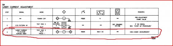
After all that, I dont think that the circuits are the same. Checking in fine detail. Dont think that the manual is available for it, so cant check that resistor, being sure its the correct one, and I dont want to just adjust the power without checking the feed voltage first (I presume anyway) to the laser, surely if the laser was not getting enough power the thing would not read the TOC etc so quickly, or am I wrong.
found the resistor, and all seems fine, reads 51mv across ir, to proove it I gently turned the laser adjust a fraction, it increased or decreased the voltage, so thats fine.
That sounds fine.
This is getting more involved, but all the steps so far have been trying to eliminate things without guessing.
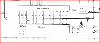
I was looking at the CD630 circuit. It's possible this problem could be caused by faulty DRAM that the data is clocked into and out of... unfortunately there's no way to prove it without swapping the DRAM chip. As always it's worth checking all the supplies, so make sure the 5 volts is exactly (within 0.2 volts) just that on the RAM chip. Also the -5 just above on the SAA chip.
This is getting more involved, but all the steps so far have been trying to eliminate things without guessing.
I was looking at the CD630 circuit. It's possible this problem could be caused by faulty DRAM that the data is clocked into and out of... unfortunately there's no way to prove it without swapping the DRAM chip. As always it's worth checking all the supplies, so make sure the 5 volts is exactly (within 0.2 volts) just that on the RAM chip. Also the -5 just above on the SAA chip.
Attachments
Will check that later, being a novice, sorry for this, where do I need to check the voltage accross? GND and one of the pins I presume on the RAM chip and the same on the SAA chip SAA chip being the filter, is that right?
So it needs to be +5 volts across the RAM chip and -5volts at the SAA chip.
Just want to get this right. So if voltages are correct, I could always purchase a new chip (do you know if they are expensive?) and try that.
Get my soldering gun out, which I enjoy, so thats fine by me.
So it needs to be +5 volts across the RAM chip and -5volts at the SAA chip.
Just want to get this right. So if voltages are correct, I could always purchase a new chip (do you know if they are expensive?) and try that.
Get my soldering gun out, which I enjoy, so thats fine by me.
That sounds fine.
This is getting more involved, but all the steps so far have been trying to eliminate things without guessing.
I was looking at the CD630 circuit. It's possible this problem could be caused by faulty DRAM that the data is clocked into and out of... unfortunately there's no way to prove it without swapping the DRAM chip. As always it's worth checking all the supplies, so make sure the 5 volts is exactly (within 0.2 volts) just that on the RAM chip. Also the -5 just above on the SAA chip.
Out of interest, does it then go through this section before it goes out to the offboard DAC? Obviously you know what you are talking about just wanted to fill my brain with as much info. as possible, as I am learning a lot, and enjoying it ALOT!, more, I think than at college, and I was at college for 3 years😱
Remember I'm looking at the cd630 diagram but all players follow the same principle.
So on the CD630 voltage is 5 volts on pin 9 of the DRAM IC. Also check pins 5 and 28 (in the piccy in post #96). Yours may use a different RAM chip but it will be conected in the same place as this, to the same points on the SAA ic.
These parts are ancient... and RAM is something that developed quickly with parts becoming obsolete overnight.
You might be better with a donor Philips machine using the same chip set to rob parts from.
You can end up throwing a lot of money at something like this so be careful 🙂
The data coming off the disc is unstable, wow and flutter if you like.
What happens is that the data is put into RAM, now once it's there it can be "clocked" out at constant speed eliminating the original variations in "speed".
This all happens in real time, the speed of the disc is compared to a crystal oscillator as an absolute reference, and by looking at the "sync" info in the data off disc to see if it's leading or lagging behind. From this an error signal can be derived to control the motor speed. That's why the CD slows down as it plays, as the laser tracks outward, if the disc rotation stayed the same then "more data" would pass the laser, so the CD format is CLV or constant linear velocity. Vinyl is CAL constant angular velocity... the needle covering more distance" per revolution at the outer edge than the inner.
So RAM is used... and in the dim and distant past I have had rare failures of RAM (as in 1 or 2 failures in all the years). There's no test that you can do to confirm or otherwise, you would have to swap the IC.
The data on all the pins is just rapid 1's and 0's... that on a 'scope look like a blur. All a 'scope might show is if the level on one or more lines were low in amplitude... then it's a case of is it the RAM, or is it the SAA ? And of course the fault may be something different.
Generally IC's are supremely reliable... but the RAM the most likely if there were a problem.
okay trying it now, not sure what to do if everything is fine, I suppose I will have to try a new chip.
Dubious though as you say they are very reliable, but its the only way that I am going to find out. Just need to find someone with one.
I have identified it as XC99659P pins starting according to my pictures on page 6 (top chip) at the bottom left, where the recessed 'blip' is.
Here goes.
Dubious though as you say they are very reliable, but its the only way that I am going to find out. Just need to find someone with one.
I have identified it as XC99659P pins starting according to my pictures on page 6 (top chip) at the bottom left, where the recessed 'blip' is.
Here goes.
- Status
- Not open for further replies.
- Home
- Source & Line
- Digital Source
- CD player with distortion. laser?