Re shielding, Jackini has a long RF hands on experience. He is aware of the implications.
From earlier years through faint memory I remember ARRL handbook saying two to three times the coil diameter was a good distance between coil and ferromagnetic housing.
All Shure, Empire, Goldring, Pickering, Stanton cartridges I’ve seen have a ferromagnetic casing as shielding.
There is a separate metal tag through which that shielding casing is electrically connected to the “negative” side of one of the coils.
On the Stanton MK V I’ve opened, there is a second copper tag that electrically connects the shielding casing with the main magnetic pole structure.
In my earlier measurements on Stanton MK V in this thread, you can see shielding casing does affect the impedance of coil and it’s frequency response (I was measuring the coil that was not connected electrically to the shielding).
Now, what is to be shielded against?
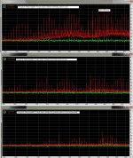
In my case, see attachments (from preliminary tests, using the Pickering in the aluminum box as in the previous photo-post #330)
George
From earlier years through faint memory I remember ARRL handbook saying two to three times the coil diameter was a good distance between coil and ferromagnetic housing.
All Shure, Empire, Goldring, Pickering, Stanton cartridges I’ve seen have a ferromagnetic casing as shielding.
There is a separate metal tag through which that shielding casing is electrically connected to the “negative” side of one of the coils.
On the Stanton MK V I’ve opened, there is a second copper tag that electrically connects the shielding casing with the main magnetic pole structure.
In my earlier measurements on Stanton MK V in this thread, you can see shielding casing does affect the impedance of coil and it’s frequency response (I was measuring the coil that was not connected electrically to the shielding).
Now, what is to be shielded against?
In my case, see attachments (from preliminary tests, using the Pickering in the aluminum box as in the previous photo-post #330)
George
Attachments
I'd assumed there was always a seam a la AT, and it was an electric field shield. But accept what you say, in which case no issue. Besides, the cookie tin being big ought to be far enough away to be loosely coupled, as davidsrb says.Grado are unshielded. Every other MM I have seen has a metal can around the generator. Some have mu metal between left and right coils. How this all changes the properties of the generator I don't know, but do have a sacrificial one so we can compare same generator with and without the can!
Still doesn't seem too clever unless there's good cause. I thought that in 2 coil-per channel arrangements, coils are generally arranged to be humbucking. I also thought that the Grado arrangement, although 2 coil, isn't humbucking but mutual inductance reduces self inductance of the coils.
LD

Is this rf? Depends on whether bandwidth is limited in the instrument, which one would hope from a noise pov. Otherwise, I get it.Re shielding, Jackini has a long RF hands on experience. He is aware of the implications.
In your rig, one coil end is (relatively) high impedance 47k. So the measured noise could have an electric field cause, and the grounded cart shield should take care of it if the correct end of the coil (with the connection to shield) is connected to the low impedance end of the rig. After all, this is what happens in normal use.Now, what is to be shielded against?
In my case, see attachments (from preliminary tests, using the Pickering in the aluminum box as in the previous photo-post #330)
If a shield is grounded, someone somewhere thinks there's an electric field issue to solve.
LD
Thanks, Bill.I can't find the pic of the ubiquitous Excel generator, but here is a mangled ortofon. And yes the coils are effectively humbucking.
The penny just dropped: a shorted turn around a humbucking pair has no effect. In a spherical cow sort of way 😉
LD
The annoying part is that in theory you could reconnect the coils for true mono. But assembly is a one way street with these. Very optimised, very irreversable!
Grado are unshielded.
Yes, I ran an experiment as an answer to the claims that LP de-magnetizers did anything. I used a huge N42 neo-magnet and a constant slew within an 1" or so of the cart and recorded the output. The output was remarkably low considering the Teslas of the field.
IIRC using the data published by Furutech we were down in the pico-volts with an LP.
IIRC, Grado have an alternate arrangement where the coils have mutual inductance and are wired in series, but with opposing winding sense. The magnetic path is arranged so that flux changes due to stylus motion have opposite sense in each coil core. And the coils are physically next to each other.
After several stiff whiskies, it can all make sense.
Lacking said whisky, I only remember the outcome: that the coil arrangement isn't humbucking, and hence I suppose the quest for shielding. But again IIRC, Grado are reported to say that the carts sound better without shielding, and now that makes sense in the context of the past few posts.
LD
In all five (US 3683128, 3694586, 3881073, 4031336, 4174111) patents of Joseph Grado issued 1972 to 1979 it is written:
“Coils in each pair are connected in voltage adding and hum canceling relation to each other”
His patents issued before 1972 show a different magnetic construction and there is not such a description of hum canceling coil arrangement
George
“Coils in each pair are connected in voltage adding and hum canceling relation to each other”
His patents issued before 1972 show a different magnetic construction and there is not such a description of hum canceling coil arrangement
George
Ah, you need more whisky, George 😉“Coils in each pair are connected in.... hum canceling relation to each other”
LD
It is a shorted turn, but VERY loosely coupled
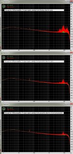
It does change the self-resonant frequency, lowers the Q. Inductance is lower by 1% @20kHz (10kHz is shown with cursor.)
(I still don't understand why there is such difficulty understanding "series-through" impedance measurement".)
Attachments
Last edited:

With all respect, what exactly do we see.Forgot to include this
The two upper curves are inductance versus frequency, resp shielded and unshielded as it seems, at what voltage applied ?
But what are the lower two curves representing ??
Hans
I don't think there is any difficulty...……….(I still don't understand why there is such difficulty understanding "series-through" impedance measurement".)
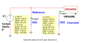
In that example, rms difference between probes 1 and 2 is 0.71mV rms, and that is what appears across the coil as the excitation potential.
The 3577A can't put out less than about 0.8mV into 50R, and pretty much that is what appears across the coil as the smallest yer gonna get.
LD
But what are the lower two curves representing ??
Phase, per the right side of the graph
Well, coil self resonance is certainly clear of the audioband. And there is a notable negative slope to inductance versus frequency. At whatever level this was made at.With all respect, what exactly do we see
That is probably real, IMO.
I think the 3577A rig could be made to produce low excitation voltage, simply by shunting the 50R impedance of the reference input with an appropriate resistor. That would form an attenuator OK for 10kHz. If the output is OK with the load, and the input can then fish the signal it needs out of the noise soup.
LD
(I still don't understand why there is such difficulty understanding "series-through" impedance measurement".)
None at all, except I have a problem with calling it inductance rather than impedance. The Q is pretty high, with the number of points plotted the slope of the phase transition might be a better measure of the Q.
I found my sacrificial AT-13Ea so I can repeat some of what I did years ago.
Last edited:
Well, coil self resonance is certainly clear of the audioband. And there is a notable negative slope to inductance versus frequency. At whatever level this was made at.
Was addressing the change of L with F. The Q of the motor winding isn't enormously high, and a function of XL,-XC, and some parallel resistance.
I still don't get it.Phase, per the right side of the graph
I would expect a curve as in the image below.
Why is your resonance peak pointing downwards instead of upwards ?
Hans
Attachments
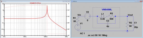
And of course I could also have taken L=50(Vin-Vout)/(Vout*6.28*freq).
This will give exactly the same outcome.
Hans
This will give exactly the same outcome.
Hans
- Status
- Not open for further replies.
- Home
- Source & Line
- Analogue Source
- Cartridge dynamic behaviour