That C is somehow not what it seems to be ?
LD
It was external 250pF||47k and the coil from an AT cartridge that I measured. If the inductance vanished at no signal the noise would vanish to the noise of the series resistance at no signal i.e. you would measure no SNR degradation with ultra-low noise bipolar op-amps until you played an LP. Come to think of it you would also observe gross noise modulation effects (I surmise).
BTW I also used an HP dynamic signal analyser but with a chart recorder (it was that long ago).
Last edited:
The noise source of the coil resistance will always be there, as will current noise arising from the preamp. I don't think anyone's claiming zero inductance at zero excitation, but it is an interesting philosophical question as to whether inductance exists at all without flux change or tends to zero. Sound of one hand clapping, yoda hears. I do get your point. But I have observed apparent correlation (inverse) between programme level and LCR resonant f that was repeatable between cartridges, which equally requires explanation otherwise.It was external 250pF||47k and the coil from an AT cartridge that I measured. If the inductance vanished at no signal the noise would vanish to the noise of the series resistance at no signal i.e. you would measure no SNR degradation with ultra-low noise bipolar op-amps until you played an LP. Come to think of it you would also observe gross noise modulation effects (I surmise).
Ah, the halcyon days when HP test equipment cost more than my house.
LD
The noise source of the coil resistance will always be there, as will current noise arising from the preamp. I don't think anyone's claiming zero inductance at zero excitation, but it is an interesting philosophical question as to whether inductance exists at all without flux change or tends to zero.
I speaking mainly to Jack's measurements. They all seem to converge on the same result at very low level and show 2 orders of magnitude reduction in L over a range that covers normal signal levels of LP play.
I wonder if the network analyser is having trouble with measuring the phase of the L/R combo at those levels?
Hmm - I am wondering if its not the instrument as well.
There must be something pretty weird going on with the BH curve to get a 2 order of magnitude change in inductance. That's akin to it being sort of centrally located at the one level and partially saturated at the other.
There must be something pretty weird going on with the BH curve to get a 2 order of magnitude change in inductance. That's akin to it being sort of centrally located at the one level and partially saturated at the other.
For context @10kHz ref 0dB = 5cm/s = 5mV after RIAAI speaking mainly to Jack's measurements. They all seem to converge on the same result at very low level and show 2 orders of magnitude reduction in L over a range that covers normal signal levels of LP play.
1mV = -28dB programme level
0.1mV = -48dB programme level
0.01mV = -68dB programme level
So in jackinnj's plots the effect is really only prevalent at low programme levels, though I'd defer to better knowledge on what levels of 10kHz are normal in programme content.
As to orders of magnitude of change, well a natural loss mechanism such as y=kx - a/x has a logarithmic roll off so I find that quite plausible in a spherical cow kind of way. More will be known if we can find the right mechanism and law.
LD
Last edited:
The lowest level of the HP3577a is -49dBm and I don't have a handy attenuator. This was a step-scan from -49dBm to -10dBm, 100 steps, with 1 Hz resolution and a pretty long scan time. The top is Channel A relative, the bottom is phase. Frequency was constant 10kHz.
I should build a little amp which would fit my measurement jig to get the results out of the weeds.
I should build a little amp which would fit my measurement jig to get the results out of the weeds.
Attachments
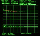
Ah, confused yoda is.The lowest level of the HP3577a is -49dBm and I don't have a handy attenuator.
Though I am definitely going through a maths dark patch, isn't -49dBm about 0.8mV into 50R ? How did you get to 30uV without an attenuator?
LD
Found my old G1042, I have few options to measure this at very low levels when some equipment comes back from calibration.
Ah, confused yoda is.
Though I am definitely going through a maths dark patch, isn't -49dBm about 0.8mV into 50R ? How did you get to 30uV without an attenuator?
LD
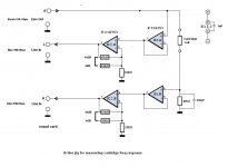
It's a series-through impedance jig, so the hind end is 50R.
The HP3577 is supposed to have a soft-key which performs the complex math, but I think it's only available when the S-parameter test set is engaged, and the low frequency is 100kHz.
The AP refuses to disclose phase below 2mV.
Attachments
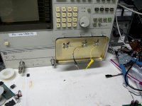
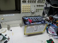

It's cookie canister from one of the boulangeries of Paris -- you have to sand the edges so that the two components conduct. the danish cookie tins are a bit cumbersome.
will mount an amplifier with switchable gain of 40 and 60dB, and two pi-attenuators inside the can (for source and the A-channel respectively).
will mount an amplifier with switchable gain of 40 and 60dB, and two pi-attenuators inside the can (for source and the A-channel respectively).
I'm sure I'm getting dumber by the day so please help me out here....It's a series-through impedance jig, so the hind end is 50R.
There's a voltage source with 50R output impedance in series with the cart coil that's in series with 50R to gnd. That means that, at 10kHz, the vast majority of the voltage source appears across the coil impedance ? So, for a -49dBm source at 10kHz into 50R tail end, that means about 1.6mV appears across the coil?
Thx
LD
Last edited:
of Paris
the danish cookie tins
What’s so special about the cookie tins from Europe? 😀
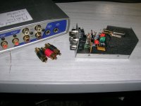
will mount an amplifier with switchable gain of 40 and 60dB,
Me too.
Currently jumper switchable btn 6dB and 40dB. I may do it as 20dB and 40dB.
George
Attachments
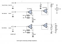
I did explain I am getting dumber, but why don't the cookie tins et al provide a shorted turn around the coil, albeit a big one ?
LD
LD
Last edited:
surely the casing of the cartridge is already a shorted turn, albeit connected to the end of one of the coils?
I did explain I am getting dumber, but why don't the cookie tins et al provide a shorted turn around the coil, albeit a big one ?
LD
res ipsit loquitor?
Actually, I was just being polite with false humility. More plainly: (a)What you have created in the shield is a shorted turn around the coil; (b) Excitation level applied to the coil is much larger than reported. The smallest level you've applied is 0.8mV not 30uV.res ipsit loquitor?
Lacking explanation otherwise, this alters results and interpretation thereof.
LD
Depends on the cart but if that's true then no issue. I didn't think it generally was, and I'd hope not. It's reported Grado hit issues trying to screen like that, for example.surely the casing of the cartridge is already a shorted turn, albeit connected to the end of one of the coils?
LD
Grado are unshielded. Every other MM I have seen has a metal can around the generator. Some have mu metal between left and right coils. How this all changes the properties of the generator I don't know, but do have a sacrificial one so we can compare same generator with and without the can!
- Status
- Not open for further replies.
- Home
- Source & Line
- Analogue Source
- Cartridge dynamic behaviour