The Stanton I dismantled had SWG48 wire (1.6 mil diam). Engineering tables show this wire handle 3.4 to 5.2 mA DC continuously.
George
George in reality the fusing currents are far greater than the published ratings. 1.5mil gold bond wire can take 100mA no problem, double 2mil Al wire .5A no problem.
Thanks a lot George,The Stanton I dismantled had SWG48 wire (1.6 mil diam). Engineering tables show this wire handle 3.4 to 5.2 mA DC continuously.
The coil of an MC is quite open to air with a few turns and very few layers (maybe single layer), so there should be no derating due to heat build up.
And I think the wire of the DL-103 is thicker than that of Stanton. I have to check it.
George
This was exactly the kind of answer I was hoping for.
Hans
Thanks Scott.
If this is data from bond wires, i.e. single wire, would it be OK to assume 1/4 that current for magnet wire on a coil with a few layers so that 85degrees C insulation won't be affected? (one more test in the q)
George
If this is data from bond wires, i.e. single wire, would it be OK to assume 1/4 that current for magnet wire on a coil with a few layers so that 85degrees C insulation won't be affected? (one more test in the q)
George
And I think the wire of the DL-103 is thicker than that of Stanton. I have to check it.
I was wrong.
DL-103 wire is thinner. It is SWG49 (1.2mil diam)
That is 1.9mA to 2.9mA DC acc to engineering tables
George
I have a spool of SWG45 (2.8mil diam) copper enamelled wire.
Engineering table says it is good for 10 to 16mA DC continuous
I thought to DC test to fusing capacity after Scott’s encouraging info.
Test 1 was slowly raising the current in steps of 20mA and holding it for 20sec at each step from 0A to fusing current .
Test 2 was continually raising the current from 0A to fussing current within 30sec.
Test 3 was continually raising the current from 0A to fussing current within 10sec.
Test No / Fusing current (A)
Test 1 / 1.723
Test 2 / 1.890
Test 3 / 1.950
During Test 1 at 1A, wire temp was around 40d C. At 1.6A it was 70-80d C.
Wire was of 10cm length, laid out straight horizontally on air.
Ambient temp 25d C, rel humidity 56 😀
George
George, the coil wire of the Denon DL-103R is 0.02mm diameter 99.9999% purity copper insulated with polyurethane varnish.
As far as I recall, the standard DL-103 uses 0.015 diameter copper (not of high purity), again with polyurethane insulation.
As far as I recall, the standard DL-103 uses 0.015 diameter copper (not of high purity), again with polyurethane insulation.
Hi Jonathan
Thank you for this hard to get info.
I checked an old DL-103 (s/n 1750).
I wrote it is SWG 49 (1.2mil, 0.03mm diam), you wrote it is even thinner between SWG53-SWG54.
I gladly trust your words.
My testing limit is 1 mil.
If I had a labeled palette of the thinnest wires I could compare visually but I don’t have these wires.
It is a good opportunity to ask you the wire size of your Lyra fine cartridges and if you have any data as to the DC current they can withstand in case of head preamplifier switch-on (Hans question).
George
George, the rated current capacity is probably extrapolated from the same codes for house/industrial wiring that is either temperature or voltage drop on a certain length run.
Most probably. On the tables, there are two current capacity values mentioned.
The lower one is based on 750 kcmil/A the higher on 500 kcmil/A
The higher one is mentioned as the absolute maximum
(kcmil =thousands of circular mil)
George
The lower one is based on 750 kcmil/A the higher on 500 kcmil/A
The higher one is mentioned as the absolute maximum
(kcmil =thousands of circular mil)
George
Hi George: in volume production we have predominately chosen 40um and 35um wire, but have employed finer gauges for prototypes and small-scale production.
Although it is possible to devise a winding apparatus that is capable of handling quite fine wire, once daily use and abuse in the field are added to the equation, it would be difficult to recommend anything smaller than 15um for volume production.
Interestingly, when winding cartridge coils, or for that matter soldering and dressing the coil leads, to an experienced cartridge builder it is obvious if the copper is high-purity or not, or whether it has been annealed, based on how it feels and handles during the building process.
Normal tough-pitch copper, or even non-annealed four-nine OFC, are harder and springier in ways that elude six-nine or higher grades, which are far more supple.
Thanks Jonathan for the feedback.
Extremely thin wires may cause after sales reliability issues.
e.g. the older DL-103 becoming silent on one or both channels due to wire break where it was touching the magnet edges. Later they installed a plastic dressing over the magnet and smoothed the plastic edges to protect the wires , I can’t say if they increased the thickness of the wire too.
There is a big difference in the feel btn annealed and not annealed copper .
I have no experience with high purity OFCs, thanks for sharing your experience.
Also good to know the Lyras use robust wire, wise choise.
George
Attachments
Thank you jackini. Very helpful post.
What is the test setup?
George
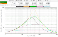
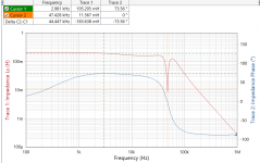
A Bode-100 Vector Network Analyzer with the source set at -10dBm, feeding a 5K caddock resistor. The caddock's are very good up to 10MHz or so.
You can see the pure inductance + shunted inductance effect and the resonance at 50kHz which gives an idea of "capacitance".
Attachments
A Bode-100 Vector Network Analyzer with the source set at -10dBm, feeding a 5K caddock resistor. The caddock's are very good up to 10MHz or so.
Something about this plot looks wrong the notch is too steep for that phase plot. The notch looks more like a vector subtraction than a resonance, can you slow down the sweep?
Also sorry to be thick but is there a picture of the test jig and exactly what is being measured?
Last edited:
Hi,
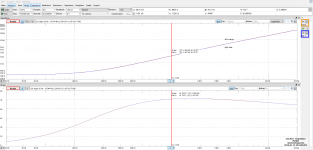
the value for the Shure´s inductance seem way too low, compared to the Datasheet.
Here´s my measurement of my old Linn K18 (AT95 Body, ATN145LC needle).
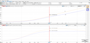
and my even oplder and probabley defect Dual DN165E (a Ortofon OM5e??)
The inductance values are here quite similar to the Datasheets .... the Linn/AT beeing a rather low-ohmic low-inductive device and the Ortofon considerably higher in values.
jauu
Calvin
ps. measured 20Hz to 20kHz, @100mV signal into 1kOhm.
the value for the Shure´s inductance seem way too low, compared to the Datasheet.
Here´s my measurement of my old Linn K18 (AT95 Body, ATN145LC needle).
and my even oplder and probabley defect Dual DN165E (a Ortofon OM5e??)
The inductance values are here quite similar to the Datasheets .... the Linn/AT beeing a rather low-ohmic low-inductive device and the Ortofon considerably higher in values.
jauu
Calvin
ps. measured 20Hz to 20kHz, @100mV signal into 1kOhm.
Attachments
Hi,
the value for the Shure´s inductance seem way too low, compared to the Datasheet.
It's two coils in parallel.
Yes, this is the crux. So would/could be generator performance and f response if the mechanism depends on slew rate, and that is 'dynamic cartridge performance' in a nutshell.Inductance may also be level dependent
To test this, one needs to f sweep at realistic programme signal levels. It's a challenge to do and measure accurately IMO, perhaps an instrumentation job.
LD
- Status
- Not open for further replies.
- Home
- Source & Line
- Analogue Source
- Cartridge dynamic behaviour