Peter, Elso!
When it comes to find the best parts, now that is your field, and I trust You.
But in a power supply for a pre, you are not forced to supply a large current, continously; you are not working into an excessively low load impedance - so why not play around with the topology, also, not only swapping parts? LC, CLC, CRC are all isolating to an extent the transformer &rectifier from the circuit. It is You, Peter, who has a great experience in this field, what have You seen up to now, regarding the sound of these different tops?
I had clearly seen the seriously detrimental effect of a raw power supply, executed in the classical way, in a dac. It took some time before I finally realized that the dense "bush" of 50 Hz related spuries, extending up to 7kHz on the screen of the analyser, is coming from the charge current spikes, not from ground loops or radiation. I put two pieces of 2.2 ohm resistor in series with the [schottky] diodes, and it has gone, totally! So why should you not use them?
george
Low ESR powersupply caps
Hello George,
I am using ultrasoft recovery diodes and 1-Ohm resistors in series with the secundaries. I am using a pi-filter (CLC) configuration.
I was just intrigued by Jocko's finding and that of Jonathan Carr.
And I want to make some pre-selection before spending a lot of money on exotic caps. 😉
Peter, For Blackgates entrance to my house is forbidden!
Elso, good practice! 
Now I understand your quest - wish you good luck, and tell us the results!
Now I understand your quest - wish you good luck, and tell us the results!
Re: Low ESR powersupply caps
In that case you might try Rubycons ZL/ZA. i played with them a bit, and they are not bad at all, but not a match for BG N caps regretabbly (although in some applications coming pretty close). And don't forget to try some Elna's as well.
Elso Kwak said:Peter, For Blackgates entrance to my house is forbidden!
In that case you might try Rubycons ZL/ZA. i played with them a bit, and they are not bad at all, but not a match for BG N caps regretabbly (although in some applications coming pretty close). And don't forget to try some Elna's as well.
Visualising charging spike
Hi George,
How did you manage to visualise the charging current spikes? I did not see anything like that on my scope.
Joseph K said:Peter, Elso!
I had clearly seen the seriously detrimental effect of a raw power supply, executed in the classical way, in a dac. It took some time before I finally realized that the dense "bush" of 50 Hz related spuries, extending up to 7kHz on the screen of the analyser, is coming from the charge current spikes, not from ground loops or radiation. I put two pieces of 2.2 ohm resistor in series with the [schottky] diodes, and it has gone, totally! So why should you not use them?
george
Hi George,
How did you manage to visualise the charging current spikes? I did not see anything like that on my scope.
janneman said:No, that is not true. An objectivist will accept a phenomenon he/she cannot explain. He only likes that the phenomenon can be consistently and reliably repeated, that establishes that it exist. Explanation would be nice, but not required to accept it.
Jan Didden
Loudspeaker designers know how to compensate for the rising impedance of the drivers, caused by the voice coil's inductance: with and RC across the driver's terminals.
And they do that repeatedly.😀
Now just think about this:
What about an RC ("snubber") across a big cap on a PSU?

Re: Visualising charging spike
Ever see something like this?
Elso Kwak said:
Hi George,
How did you manage to visualise the charging current spikes? I did not see anything like that on my scope.
Ever see something like this?
An externally hosted image should be here but it was not working when we last tested it.
Hi!
Jackinnj, I would like to solicit you again, to disclose to us poor public, your measurement setup! I was never able to produce such a nice stable picture of this ringing! 🙂 🙂 but then
Elso! There are, again, two different things here. Measurement of the current pulses re-charging the reservoir cap - this can be done by several ways. It is possible to wrap a small coil around the wire connecting the diode to the cap, or simply putting a small value series resistor there. With the coil, you have to compensate for it's response; with the resistor, it will change by it's resistance the current generated. In a small power system I was putting something like .05 ohm, and hoping that this value will not change too much the original impedances. Then the best way to look at the small voltage developed across this resistance, is to look at it with two probes, in differential mode. [but you can put the R between cap - ground, as well, then you don't need differential]
It was very educational, for me, looking at it, while driving the amplifier with different signals. These pulses are in the range of several [1- 6] msecs, depending on the loop parameters and the load current. their height is ~ 0.5 - 10 amps, again depending on those up above. And they are mixing with the amplifier output signal current, halfwave- rectified..
Jackinnj has demonstrated here, instead, that small portion of the signal, that "snitch", which is caused by the diodes reverse current at the switch-off. This is more difficoult to see, because of the presence of the contemporary large amplitude signals of the secondary. This "snitch" is present on the charge current pulses, and on the secondary voltage waveforms, as well. On the secondary, ~ sinusoidal [!?] waveforms, you see the peak cut off, like if it were going into clipping - that is where the recharging takes place. At the end of this plateau, you see the spikes, what is on the pic of Jackinnj.
You can sniff these signals by putting a ~ 5- 10 nF small cap, on the cap - rectifier joint, the cap then terminated to ground in ~ 3 kohm.
This way you eliminate the large value, low frequency part, and have a clear view of the HF part.
As it is visible on the pic up above, the resonance freq. is ~ 9Mhz, at that setup.
And again, the "snubber" of Carlos does not eliminate this.
I have some pictures, not so nice like those of Jackinnj, maybe will put them on here later.
Ciao, george
Forgot to mention, that while looking at those signals, it is best to trigger on the line - that is, switch the scope trigger input selector to "line".
Visualising Ringing
I put the probe across the 1-Ohm resistors even made them as small as 0.125-Ohm and I do see the charging peaks but NO RINGING!
😕
Hi ,Joseph K said:Forgot to mention, that while looking at those signals, it is best to trigger on the line - that is, switch the scope trigger input selector to "line".
I put the probe across the 1-Ohm resistors even made them as small as 0.125-Ohm and I do see the charging peaks but NO RINGING!
😕
Going back to my very first post, I haven't yet gathered what possible purpose the single 100 nF non--snubbered cap does in the carlos(tm) power supply.Joseph K said:As it is visible on the pic up above, the resonance freq. is ~ 9Mhz, at that setup.
And again, the "snubber" of Carlos does not eliminate this.
100 nF// 100 uF (or more) produces a peak and a dip.
100nF+1 R//100 nF// 100 uF (or more) produces a peak and a dip but the peak is moved and is a bit smaller.
100 nF+ 1R// 100 uF (or more) produces a flat response.
What I mean is, what is the benefit of the snubber if you have one 100 nF in parallel without a resistor?
The conlusion must be that no high-Q cap (100nF or less) should have a resistor.
Optimal power supply, per rail:
4700 uF (2200-10000 uF) // 100 nF+1R --------- (traces, cables)----100 uF//(100F+1R)
The seems to be a PS wiith killed resonance peaks but with dips.
My point (technically) this 100 nF alone in the PS is rather unecessary?
Re: Visualising Ringing
I have done the same long time ago and from I remember I got pretty clean current pulses, no visisble ringing with used scale on the oscilloscope.Elso Kwak said:
Hi ,
I put the probe across the 1-Ohm rersistors even made them as small as 0.125-Ohm and I do see the charging peaks but NO RINGING!
😕
Elso, Peranders!
The presence of ringing is depending on the tank circuit, and the signal exciting it.
the tank circuit is always there: trf. secondary leakage inductance, stray capacitance, diodes reverse capacitance.
You decrease the signal exciting it by: decreasing the forward current pulse, applying better diodes with less reverse recovery snap. Elso, you did both, no wonder if you have to search hard!
But try to put together a mockup supply, like I did: [if you are looking for spikes]
~200 VA , 2 * 24 VAC, + MUR860 rectifiers + 20000 uF reservoir cap, short fat wires, => and report back now, please!
We are talking about a "high - cap" supply, by now, if I am not mistaken..
Joseph K said:Hi!
Jackinnj, I would like to solicit you again, to disclose to us poor public, your measurement setup! I was never able to produce such a nice stable picture of this ringing! 🙂 🙂 but then
I took the picture from POWER 456's Snubber Design Application and have never gotten the nice picture like Dr. Riddley has! I think he must have done this in a room with a Faraday shield.
I have simulated it the ringing in Multisim, but when I try to look at it -- it's more like noise (as Jan pointed out). the two snapshots below are just AC coupled views of the ripple voltage with the probe on the diode anode or cathode as the case may be, referenced to ground.
An externally hosted image should be here but it was not working when we last tested it.
The pix above were made with a Tek DSO. I don't have a differential probe for this unit. I do have a current probe for my 2465, but with that scope I have to get out my digital camera -- perhaps later today.
The noise you have got there is generated some where else. Computer, TV, "tube"-lamp, computer monitor, switched power supply somewhere, mobile phone etc etc?
Have you tried to shut down every noise source you have got? Have you minimized the loop created by the ground cable of your oscilloscope probe?
Have you tried to shut down every noise source you have got? Have you minimized the loop created by the ground cable of your oscilloscope probe?
peranders said:The noise you have got there is generated some where else. Computer, TV, "tube"-lamp, computer monitor, switched power supply somewhere, mobile phone etc etc?
Have you tried to shut down every noise source you have got? Have you minimized the loop created by the ground cable of your oscilloscope probe?
I ran a quick spectrum analysis of the AC input before I did the test -- it was quiet -- I know that Jim Williams at Linear Tech uses an analog scope and attaches a piece of RG58/U directly to the points of interest -- this is where cookie tins for shielding become handy 🙂 .
Here's an example which I put up before:
An externally hosted image should be here but it was not working when we last tested it.
this is the transformer and inductor -- the power supply weights around 35 kG, the CT inductor is 1 mH:
An externally hosted image should be here but it was not working when we last tested it.
Guys, you have made me busy...
And now I will contaminate the forum again..
Here are some preliminary pics about my best efforts to illustrate what we have been talking about:
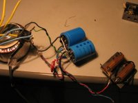
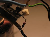
First, the test setup:
Classic style power supply, high current rectifier bridge, 2*24 VAC, 2* 20000 uF reservoir caps.
Made in a hurry, [ugly, pardon me].
I am sniffing at the power AC, with respect to ground [transformer central tap].
And now I will contaminate the forum again..
Here are some preliminary pics about my best efforts to illustrate what we have been talking about:
First, the test setup:
Classic style power supply, high current rectifier bridge, 2*24 VAC, 2* 20000 uF reservoir caps.
Made in a hurry, [ugly, pardon me].
I am sniffing at the power AC, with respect to ground [transformer central tap].
Attachments
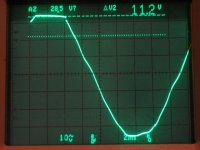
This how the AC signal looks like. It is assymmetric, because I only load the positive power rail. the load was visible before, it is 20 ohm Dale power resistor.
On top you see the sinus "de-capped". At the end of the plateau, there is the glitch. Note the value of it, I've put the markers on it!
On top you see the sinus "de-capped". At the end of the plateau, there is the glitch. Note the value of it, I've put the markers on it!
Attachments
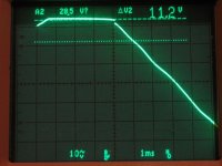
The same again, more close:
Note, that the width of this plateau is the duration of the recharge current pulse. The lenght of it depends on the signal current flowing into the load: with higher output this plateau is increasing, with lower output signal it is narrower, it stops at around 2-3 msec. Now, you have that spike rigorously attached to the end of it, with it's relative phase [and amplitude] modulated by the output signal!
Note, that the width of this plateau is the duration of the recharge current pulse. The lenght of it depends on the signal current flowing into the load: with higher output this plateau is increasing, with lower output signal it is narrower, it stops at around 2-3 msec. Now, you have that spike rigorously attached to the end of it, with it's relative phase [and amplitude] modulated by the output signal!
Attachments
- Status
- Not open for further replies.
- Home
- Amplifiers
- Chip Amps
- Carlos' snubberized Gainclone Power supply