Konnichiwa,
ESL is unrealistically low IMHO. The rather supreme Siemens/Epcos "Silver" Cap's clock in at around 9nH even at low capacitor values. I'm not sure even SMD Ceramics qite match 3nH....
Sayonara
mikelm said:here are some spice results I have ended up after some playing
do we think that the cap values ( esl / esr ) are realistic ?
ESL is unrealistically low IMHO. The rather supreme Siemens/Epcos "Silver" Cap's clock in at around 9nH even at low capacitor values. I'm not sure even SMD Ceramics qite match 3nH....
Sayonara
motherone said:I'm with you two. I'd like to see what actually changes on the amp with these mods. I'd also like to see the regulated 3886 thrown in as well.[snip]
Actually, in the case of a regulated GC (or any amp, this is electronics, and they don't know we named the thing GC, nor do they care), this may be an entirely different and interesting case.
These 'snubber' networks used after a regulator can help stabilise the control/regulation loop. In fact, in the 1994 Audio Amateur series that I co-authored, I found that using very high quality film caps at the reg output (in parallel with the customary elcap) made the reg perform worse, more overshoot, quicker oscillations etc. The reason was that the filmcap shorted out the lossy ESR component of the elcap that damped the loop. So we ended up advising AGAINST using very hi quality film caps here; with just the avarage elcap (IIRC we advised Panasonic HQ's) things were OK.
So, depending on how you have terminated your reg circuit, it may be improved by using an R-C duo at the output. Or just snip out that expensive film cap. And the improvement *could* have audible effects, an oscillating reg loop (which is not always obvious without detailed testing) definitely wouldn't make your amp happy at all...
Jan Didden
Kuei Yang Wang said:ESL is unrealistically low IMHO. The rather supreme Siemens/Epcos "Silver" Cap's clock in at around 9nH even at low capacitor values. I'm not sure even SMD Ceramics qite match 3nH....
Hi Kuei - thanks for the input, I will play about with slightly higher values in spice before I test to see if this actually sounds good.
mike
What is deal with this " monkey bussines ", Mike ? I see only, that higher impedance is only shifed up to higher frequency.
janneman said:
In fact, in the 1994 Audio Amateur series that I co-authored, I found that using very high quality film caps at the reg output (in parallel with the customary elcap) made the reg perform worse, more overshoot, quicker oscillations etc. The reason was that the filmcap shorted out the lossy ESR component of the elcap that damped the loop. So we ended up advising AGAINST using very hi quality film caps here; with just the avarage elcap (IIRC we advised Panasonic HQ's) things were OK.
Jan Didden
Unfortunately, Jan, Walt, Gary etc are rigorous empiricists 🙂 (a good thing in my view) but the world of high end DIY seems to be ruled by subjectivists.
you might be right - when I have redesigned and built it I will report what I find subjectively...🙂Upupa Epops said:What is deal with this " monkey bussines ", Mike ? I see only, that higher impedance is only shifed up to higher frequency.
I thought low impedance up to 10 meg would be advantagous and of course actually impedances at all frequencies are dropping. There should be no disadvantage - should there ?
cheers
mike
To Mike : Sure, you don't damage nothing with this and we must wait for listening results. But I mean, that all is rather " supplymania " without realy proved results, becouse in each construction is too much variable.
Carlos!
welcome back!
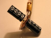
Thorsten, when I said "mirrored capacitors", I wanted to say, in your words, "capacitors end to end". I have been looking at your pic taken earlier, and tried to do the same. May I point you at the photo in
post 432?
There you see the blue caps put "end to end". The results are in post 439.
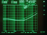
In that graph, the highlighted trace is the simple parallel config, shown in post 438.
the second trace, which shows actually higher inductance, is the "caps end to end"
Now, it was a strange result, and I felt like I should repeat it.
Here it is an another config:
welcome back!
Thorsten, when I said "mirrored capacitors", I wanted to say, in your words, "capacitors end to end". I have been looking at your pic taken earlier, and tried to do the same. May I point you at the photo in
post 432?
There you see the blue caps put "end to end". The results are in post 439.
In that graph, the highlighted trace is the simple parallel config, shown in post 438.
the second trace, which shows actually higher inductance, is the "caps end to end"
Now, it was a strange result, and I felt like I should repeat it.
Here it is an another config:
Attachments
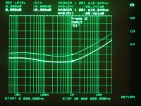
The highlighted trace here is the caps end to end, or "mirrored", the other one is the parallel config. What you see here is a bit better ESL for the "mirror" config, but! The mirror config also means, that now the "bulk" of the caps is closer to the measurement points, covering less loop area. In case of the parallel config, the second cap causes the loop to be more extended. So, I would say, that the only change seen here is because of the loop geometry changing. Though, as you can see, I tried my best to create something with low stray inductances.
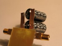
Now, how this all compares to a setup, with caps paralleled in the conventional way, but the shortest leads possible?
Now, how this all compares to a setup, with caps paralleled in the conventional way, but the shortest leads possible?
Attachments
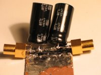
Here is the result of comparing the previus test setup with "mirrored" capacitors to the classic paralleled in an optimal way:
The selected trace is the parallel, classic, the upper trace is the parallel, mirrored.
What I see here is that some mm of a good, low inductance foil & increased loop area is far more detrimental then the orientation of the caps!
The selected trace is the parallel, classic, the upper trace is the parallel, mirrored.
What I see here is that some mm of a good, low inductance foil & increased loop area is far more detrimental then the orientation of the caps!
Attachments
Joseph, could you please show us how your cables look like. How does it look when you have the contacts soldered together and you have no extra parts at all?
So, for me it is quite clear: BG Super E config = 6 dB deeper down into your pocket.
In the meantime, shame on me that only now, I discovered the thoughts of Bruno Putzeys about this same thing:
Bruno about BG-s
I can only suggest with all my heart to read all his works 😉
I even think that why was I doing this, when it was already done & written here, on this forum?
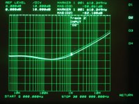
One thing anyway came clear from these tests: The capacitor ESL in itself is nothing compared to the stray inductances in the wiring of an average DIY setup, or even in an "industrial" realization. While, on your last pic, Thorsten, your friend lost some serious money, gained some extra ESL while connecting that combo to the pins 😉
But, anyway, it was an interesting ride, thanks again, Thorsten!
In the meantime, shame on me that only now, I discovered the thoughts of Bruno Putzeys about this same thing:
Bruno about BG-s
I can only suggest with all my heart to read all his works 😉
I even think that why was I doing this, when it was already done & written here, on this forum?
One thing anyway came clear from these tests: The capacitor ESL in itself is nothing compared to the stray inductances in the wiring of an average DIY setup, or even in an "industrial" realization. While, on your last pic, Thorsten, your friend lost some serious money, gained some extra ESL while connecting that combo to the pins 😉
But, anyway, it was an interesting ride, thanks again, Thorsten!
Peranders, if You look at the pic in post 471, there you see the lemo female connectors. Then I attach to them two short, thin, 50 ohm Lemo male connector equipped cables, and they go into the analyser,as in post 402.
http://www.diyaudio.com/forums/showthread.php?postid=551714#post551714
http://www.diyaudio.com/forums/showthread.php?postid=551714#post551714
Sorry but I don't see any graph over the contacts alone. Am I blind?
My main point was how much S/N sort of speaking you have with this fine instrument. How much are you above the "resolution"?
I think you have should very good that compactness normally is a very good thing and sometimes essential in order to succeed.... so ratsnets (big ones) often not are positive.
The reason was that the filmcap shorted out the lossy ESR component of the elcap that damped the loop. So we ended up advising AGAINST using very hi quality film caps here; with just the avarage elcap (IIRC we advised Panasonic HQ's) things were OK.
Jan, again, I could not agree with You more!
May I add, that in my opinion not only after such a regulator, but almost everywhere the high Q [not only quality] film caps will cause ringing & phase shifts, when applied like bypass. This will not cause malfunctions, but might be heard.
I would think that a general practice of using a small value damping resistor would really save these situations. Stability- wize. I did not do tests.
And I was really happy to see Mikelm picking up this thought and start to integrate them into that combo! though maybe it really is a bit overcomplicated.

- Status
- Not open for further replies.
- Home
- Amplifiers
- Chip Amps
- Carlos' snubberized Gainclone Power supply