Ps.: I will have to look into this last effect more in depht, in the future!
I would like to really exclude all possible measurement errors.
good night!
I would like to really exclude all possible measurement errors.
good night!
Aya, what a shame! I have made of myself such a fool!
After these posts, I continued thinking and it came to my mind, that this L - cancellation effect, I did not check the relationships between the original, one cap resonance value, and the new resonance value for the series connected cap. What can be expected is that it remains the same, because in the LC product L is doubled, C is halved.
Now I checked it again, and it came out, that the higher value, for the cap in example, the ~ 15 MHz, is the ORIGINAL resonance point, and the resonance value found for the "A" config, that is, the ~ 13 MHz is shifted down from the original.
So, I just measured the INCREASED inductance because of the greater loop area, inthe case of the " A " config, not the DECREASED inductance in the " // " case!
So, what seems to be remained valid here, between the ruins, is that I was not able to measure any difference up to now, in any case, with an exception, maybe, for the last problem, but now I will have to check very thoroughly, again!!!! 😱
Curva, on post 404 of this thread you can have a look of the usual setup in my testing. As you can see there, I am not using scope probes, as, in fact I am not using a scope, as well..
What you see there is the analyser measurement ports, port 1 & port2, which are professional N-type connectors. then I put on them a converter to BNC then to lemo, all this keeping the caharacteristic 50 impedance untouched. {khm.. but actually, not deteriorating too much}
So, about the part of testing of the conventional Super E config, I am quite sure in that I did not see any change in ESL, or in other words, in that "inner resonance" of the caps emphasised so much in Jelmax papers. So, no L-cancelling.
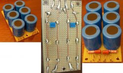
In normal caps tested by me, in the suggested Super E config.
Here, because I was able to use short leads, then only swap the orientation of one of the caps put in parallel, so not changing lead lenghts & geometry of the setup, I positively did not see changes regarding ESL.
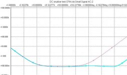
Now, there was the error committed by me, which consisted of arriving at a conclusion & putting that here without rigorously cross checking before. This regards that "L-cancellation" seen by me in series connected caps. No, it's non existent as well, there I comitted a measurement error. With the series connection of the caps, and then pulling them apart a bit, I changed the geometry of the loop formed by the to caps, so I introduced extra L, which has then shown up nicely in the impedance graph, shifting down the resonace point.
Then there is the last setup, suggested by Thorsten, looking for any inductance changes while "mirroring" two capacitors. Here there is confusion, I have seen the L increasing again, and I am suspecting of a measurement error again, although here I was cautious.
So, I am ashamed of myself being carried away for a moment, and have put that material up on here. My only consolence is that maybe you can use it as an example of an ugly error to avoid...
and, as an example of how sensitive are these circuits of the actual geometry..
cheers, george
What you see there is the analyser measurement ports, port 1 & port2, which are professional N-type connectors. then I put on them a converter to BNC then to lemo, all this keeping the caharacteristic 50 impedance untouched. {khm.. but actually, not deteriorating too much}
So, about the part of testing of the conventional Super E config, I am quite sure in that I did not see any change in ESL, or in other words, in that "inner resonance" of the caps emphasised so much in Jelmax papers. So, no L-cancelling.
In normal caps tested by me, in the suggested Super E config.
Here, because I was able to use short leads, then only swap the orientation of one of the caps put in parallel, so not changing lead lenghts & geometry of the setup, I positively did not see changes regarding ESL.
Now, there was the error committed by me, which consisted of arriving at a conclusion & putting that here without rigorously cross checking before. This regards that "L-cancellation" seen by me in series connected caps. No, it's non existent as well, there I comitted a measurement error. With the series connection of the caps, and then pulling them apart a bit, I changed the geometry of the loop formed by the to caps, so I introduced extra L, which has then shown up nicely in the impedance graph, shifting down the resonace point.
Then there is the last setup, suggested by Thorsten, looking for any inductance changes while "mirroring" two capacitors. Here there is confusion, I have seen the L increasing again, and I am suspecting of a measurement error again, although here I was cautious.
So, I am ashamed of myself being carried away for a moment, and have put that material up on here. My only consolence is that maybe you can use it as an example of an ugly error to avoid...
and, as an example of how sensitive are these circuits of the actual geometry..
cheers, george
Joseph K said:[snip]Now, there was the error committed by me, which consisted of arriving at a conclusion & putting that here without rigorously cross checking before. This regards that "L-cancellation" seen by me in series connected caps. No, it's non existent as well, there I comitted a measurement error.
[snip]So, I am ashamed of myself being carried away for a moment, and have put that material up on here. My only consolence is that maybe you can use it as an example of an ugly error to avoid...
and, as an example of how sensitive are these circuits of the actual geometry..
cheers, george
George,
You showed a very strong committment to checking, rechecking and being VERY critical of your own results. This is an attitude I find sorely lacking in most of the posts around here.
It is for me another reason to take your results very seriously indeed, confident that if you are sure about the results, they very probably are correct.
Thanks again for your inputs.
Jan Didden
Thanks, Jan, it's very kind of You.
By the way, in the previous post I was really thinking to re-quote your motto, it fits here so well...
[qoute]/ "I think the most important experience you have as an experimental scientist is realising the extent to which you can be fooled, the extent to which your impulses and aspirations lead you to believe things which have nothing to do with the way things actually work" - Harvard Professor of Biology Mark Ptashne on winning the Nobel Prize for DNA sequencing.[/quote]
You showed a very strong committment to checking, rechecking and being VERY critical of your own results. This is an attitude I find sorely lacking in most of the posts around here.
Indeed. Atleast he did not say "you just dont get it" or "try it out yourself", "why should I do your work". From what this forum has seen lately, that attitude alone was worth his weight in gold, let alone the results. Hope it is contagious and spreads around (especially to a few people more than others).
but further to Jan's point -- utilizing rigorous empirical method we can ascertain the correct values -- too small a value and there is no clamping action, too large a value and energy is wasted, components are stressed and there is a possibility of RFI, EMI.
I guess that what we have to say now is that "snubberization" is important because the high frequency ringing can overload drive circuits (particularly a GC with a gain of 20dB), can leak backwards from the power supply of the DUT into other power supplies, can radiate from the filter capacitors etc. etc.
I guess that what we have to say now is that "snubberization" is important because the high frequency ringing can overload drive circuits (particularly a GC with a gain of 20dB), can leak backwards from the power supply of the DUT into other power supplies, can radiate from the filter capacitors etc. etc.
Dear jackinnj,
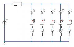
I noticed your nice efforts to "advertise" a proper application of snubbing here. But I would like to warn you, that in our case, or rather, Carlos's case, this C // R-C filter combination is NOT a snubber, because it is applicated at the wrong place, with regards of snubbing the resonant circuit BEFORE the diode bridge.
The proper snubbing is done at the transformer secondary, and in it's original function
This is the - original -reason of putting together such a combination, and this is why Peranders did not understand, what the heck would all this mean on the reservoir cap. Now, that article quoted by Carlos, is flawed in quite a several points, and was NOT talking about a proper snubbing of the tank circuit formed by the transformer leakage inductance, the transformer secondary stray capacitance, the diodes reverse capacitance. It was NOT talking about that nice FM modulated [by the output signal] noise generator mechanism, which is exciting this tank circuit, and is providing a noise spectrum up to the MHz region.
You know about it, I know about it, many of us know about it. The methods and measurements described by You are adequate for
attenuating this effect, but ARE NOT APPLIED here in the first place!
I was looking at it, as well, I was measuring the noise spectrum on the rectifier - transf. secondary node, I have seen the result of putting a snubber there, [it is "noise shaping" the spectrum] and I was looking for the effect of putting that same snubber on the large reservoir cap, instead of the rectifiers. It DOES NOT have any effect on that power spectrum, applied on the reservoir cap!
Now, again, I did not want to attack anybody, I am just saying, that it should be clear, that an another possible explanation is excluded, again, after my tests, which have excluded a possible explanation in the chip's bypass structure.
Now, from this it can be seen, that we have a noise generated up to the MHz region, it is not attenuated or eliminated by a proper snubbing action, then we know that without that R- C the C in itself forms a resonant circuit on the reservoir cap, and now we apply the "snubber", the R- C combo, which will damp this resonating tank.
For me this sounds like it could have an effect on the sound.
And do not forget, that this noise generated by the snapping diodes is frequency modulated by the output [audio] signal!
This "snubber" applied here also does not take care of the high current pulses re- charging the reservoir cap, and there effect on the circulating audio current, cross - modulated by these pulses across the capacitor's ESR.[ which is highly non linear..]
Oh, how much I miss now Carlos from this thread! And Fred, who could put it all in place... and would be badly needed in this forum, like the lion for the antilops, like the wolf to the sheep, like the cat for the mice!! Who will rappresent the coercitive force of intelligence described by Darwin so nicely..
best regards, george
I noticed your nice efforts to "advertise" a proper application of snubbing here. But I would like to warn you, that in our case, or rather, Carlos's case, this C // R-C filter combination is NOT a snubber, because it is applicated at the wrong place, with regards of snubbing the resonant circuit BEFORE the diode bridge.
The proper snubbing is done at the transformer secondary, and in it's original function
- is shifting down the resonant frequency by applicating C
- then snubbing the parallel tank circuit applicating the R -C combo
This is the - original -reason of putting together such a combination, and this is why Peranders did not understand, what the heck would all this mean on the reservoir cap. Now, that article quoted by Carlos, is flawed in quite a several points, and was NOT talking about a proper snubbing of the tank circuit formed by the transformer leakage inductance, the transformer secondary stray capacitance, the diodes reverse capacitance. It was NOT talking about that nice FM modulated [by the output signal] noise generator mechanism, which is exciting this tank circuit, and is providing a noise spectrum up to the MHz region.
You know about it, I know about it, many of us know about it. The methods and measurements described by You are adequate for
attenuating this effect, but ARE NOT APPLIED here in the first place!
I was looking at it, as well, I was measuring the noise spectrum on the rectifier - transf. secondary node, I have seen the result of putting a snubber there, [it is "noise shaping" the spectrum] and I was looking for the effect of putting that same snubber on the large reservoir cap, instead of the rectifiers. It DOES NOT have any effect on that power spectrum, applied on the reservoir cap!
Now, again, I did not want to attack anybody, I am just saying, that it should be clear, that an another possible explanation is excluded, again, after my tests, which have excluded a possible explanation in the chip's bypass structure.
Now, from this it can be seen, that we have a noise generated up to the MHz region, it is not attenuated or eliminated by a proper snubbing action, then we know that without that R- C the C in itself forms a resonant circuit on the reservoir cap, and now we apply the "snubber", the R- C combo, which will damp this resonating tank.
For me this sounds like it could have an effect on the sound.
And do not forget, that this noise generated by the snapping diodes is frequency modulated by the output [audio] signal!
This "snubber" applied here also does not take care of the high current pulses re- charging the reservoir cap, and there effect on the circulating audio current, cross - modulated by these pulses across the capacitor's ESR.[ which is highly non linear..]
Oh, how much I miss now Carlos from this thread! And Fred, who could put it all in place... and would be badly needed in this forum, like the lion for the antilops, like the wolf to the sheep, like the cat for the mice!! Who will rappresent the coercitive force of intelligence described by Darwin so nicely..
best regards, george
Joseph K said:Dear jackinnj,
I noticed your nice efforts to "advertise" a proper application of snubbing here. But I would like to warn you, that in our case, or rather, Carlos's case, this C // R-C filter combination is NOT a snubber, because it is applicated at the wrong place, with regards of snubbing the resonant circuit BEFORE the diode bridge.
George -- i tried to make the etymological distinction between a snubber and a zobel at the start of this thread, and concur with your statement. too bad there isn't an emoticon tipping it's hat!

Hello all,
I've read this thread up to page 34. Still a little way to go... But I could not wait till "the end of the movie" to ask a rather simple question:
- If one builds two chip amps, one DUT (design under test) with snubber, one RD (reference design),
- plug the same dummy load on'em
- then feed the two designs with the same source,
- what would say an oscillocope or a spectrum analyser as of the voltage between the two outputs?
Good question but I think the answer is right now: Nobody knows. I'm also very interested if there is a possibility to show this in measurements.
I'm with you two. I'd like to see what actually changes on the amp with these mods. I'd also like to see the regulated 3886 thrown in as well.
Unfortunately, I don't have access to a scope, nor do I know the first thing on how to test this stuff properly, or I'd start venturing towards it myself. I'm sure others on here can do it much more quickly and competently than I can.
I'd also like to see if anyone has a more optimized value based on some formula than the one Carlos arrived at by trial and error. Heck, it'd be pretty cool to see the effects of the different values of the snubbers on a scope if someone can manage that as well.
Konnichiwa,
No, this was actually not what I asked.
Let me explain my thoughts originally.
I had seen the "super e-cap" in a number of pieces of tube gear, here an example:
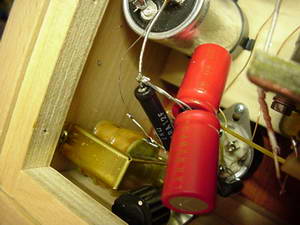
So, I has always seen the "super e-cap" with the capacitors end-to-end.
Now if we take a radial electrolytic capacitor we find that if mount two end to end as shown above the windings of the capacitors are in opposing direction (regardless of polarity of connection BTW) but with the actual magentic axis of the resulting coils aligned.
The next round of my thinking went:
"If there is a material magnetc field with suitable alignment but reverse polarity it would cancel, as would inductance."
What I wanted to know if that was so, in which case the "super E cap" configuration could be a neat way to get low ESL from parallel conventional cap's. I have not quite followed if we have now established that this is not so or if we remain uncertain.
Now the total "Super E Cap" effect may be 6db lower ESR and 6db lower ESL and 6db higher cashflow for Jelmax/BG/Rubycon. Or there may be something special to the capacitor structure or whatever....
Oh I forgot, thanks for taking thr trouble measuring all of this. It was certainly very instructive.
Sayonara
Joseph K said:and now I would like to turn back to Thorsten's original setup. As far as I understood, he asked me to measure the " mirrored" two electrolytics config with respect to the classical, parallelled setup.
No, this was actually not what I asked.
Let me explain my thoughts originally.
I had seen the "super e-cap" in a number of pieces of tube gear, here an example:
So, I has always seen the "super e-cap" with the capacitors end-to-end.
Now if we take a radial electrolytic capacitor we find that if mount two end to end as shown above the windings of the capacitors are in opposing direction (regardless of polarity of connection BTW) but with the actual magentic axis of the resulting coils aligned.
The next round of my thinking went:
"If there is a material magnetc field with suitable alignment but reverse polarity it would cancel, as would inductance."
What I wanted to know if that was so, in which case the "super E cap" configuration could be a neat way to get low ESL from parallel conventional cap's. I have not quite followed if we have now established that this is not so or if we remain uncertain.
Now the total "Super E Cap" effect may be 6db lower ESR and 6db lower ESL and 6db higher cashflow for Jelmax/BG/Rubycon. Or there may be something special to the capacitor structure or whatever....
Oh I forgot, thanks for taking thr trouble measuring all of this. It was certainly very instructive.
Sayonara

- Status
- Not open for further replies.
- Home
- Amplifiers
- Chip Amps
- Carlos' snubberized Gainclone Power supply