Thorsten,
have you try the effect on doing that "Super E-Cap" style configuration with a good effect? (without knowing the measurement result?)
As per Thorsten idea,
maybe somebody with excess Panasonic FC 1500uF caps and the BrianGT's board can try the configuration directly? with as close as possible soldering the cap under the top cap?
Regards,
---
David
Attachments

Re: AND NOW FOR SOMETHING COMPLETELY DIFFERENT
Kuei, the snubber deals with the ESL not only of the caps, it's more than that.😉

Kuei Yang Wang said:If we can significantly reduce the ESL in electrlytics by mechanical layout, maybe we don't need no sintinkin snubbers, bypasses and all that jazz?
Sayonara
Kuei, the snubber deals with the ESL not only of the caps, it's more than that.😉
Hi,
here is the one of the many inductance calculators on the net. You will find that ESL of the electrolytics is not the main concern. It is much more probable that the snubber with 2W resistor will have greater parasitic inductance than good electrolytic. And there is also wiring inductance. So, if you think that inductance is the problem, four layer PCB with dedicated ground and power planes is the way to go. Now this post has nothing to do with audiability of the snubber, but everything with the presumption that ESL of the electrolytic is the problem.
Best regards,
Jaka Racman
Jaka Racman said:Hi,
here is the one of the many inductance calculators on the net. You will find that ESL of the electrolytics is not the main concern. It is much more probable that the snubber with 2W resistor will have greater parasitic inductance than good electrolytic. And there is also wiring inductance. So, if you think that inductance is the problem, four layer PCB with dedicated ground and power planes is the way to go. Now this post has nothing to do with audiability of the snubber, but everything with the presumption that ESL of the electrolytic is the problem.
Best regards,
Jaka Racman
Jaka,
You are right. If you look at Joseph K's tests pictures, he takes great care in measuring directly at the components, with as little as possible wiring. He obviously knows very well what he is doing.
This will not always be possible in an amp implementation. If you are not able to keep the wiring to the snubber components VERY small (and that includes of course the component wires from, say, the resistor) you are going backwards. To get the measured values of Joseph you need quite a specific layout.
Jan Didden
You guys keep discussing if you want, I'm out.
I'm under moderation, if you see this post, it has passed by a censorship agent.
Cheers and thanks for the fish.😎
I'm under moderation, if you see this post, it has passed by a censorship agent.
Cheers and thanks for the fish.😎
Has anyone considered *adding* inductance? For example, small RF hash chokes between the large rectification caps and the remaining chain clearly defines the inductance looking back towards the transformer permitting easier sim and design, isolates the circuit from any funny stuff happening back there in the ultrasonics and better filters noise in the RF band. On the basis of this thread I've been playing with the concept on a flea-power tube amp and it appears to have a lot of sonic merit. Small value, high current hash chokes typically have DCR's in the .1-.2 ohm range, which might also assist in damping HF peaks. I'd run some sims to confirm, but I'm late for work. 🙂
Jaka Racman said:Hi,
here is the one of the many inductance calculators on the net. You will find that ESL of the electrolytics is not the main concern. It is much more probable that the snubber with 2W resistor will have greater parasitic inductance than good electrolytic. And there is also wiring inductance. So, if you think that inductance is the problem, four layer PCB with dedicated ground and power planes is the way to go. Now this post has nothing to do with audiability of the snubber, but everything with the presumption that ESL of the electrolytic is the problem.
Best regards,
Jaka Racman
It is not ESL he said.

Jan seconded. 😱
But both of them do not know what it is then! 😀
I continue to learn less thru your posts guys.

Meanwhile, I am enjoying my GC with snubd PSU! 😎
There is no stopping them - carlos! 🙄
aHobbit said:
It is not ESL he said.
Jan seconded. 😱
But both of them do not know what it is then! 😀
I continue to learn less thru your posts guys.
Meanwhile, I am enjoying my GC with snubd PSU! 😎
There is no stopping them - carlos! 🙄
I am confused. Do you think it is not a good idea to figure out what is happening that makes this sound good?
Doing so may help produce an even better sound with the LM3886 (this may be a local maximum and there is an even better combination out there) or make it easier to implement in a different chip or part layout.
I am enjoying music as I read this and am still very interested in understanding what is happening and why it works.
What is your point?
moving_electron said:I am confused. Do you think it is not a good idea to figure out what is happening that makes this sound good?
[snip]
To speak for myself: I am interested to find out the mechanics of the electrical influences. But, I ams also interested to find out if in fact it does change the sound, and if so, under which specific sets of circumstances. In other words, in MY GC, can it be expected to change the sound? Why don't I hear it? What is different in my set-up? I don't see an easy way to find out. Now, if we could identify an elctrical change at the GC (or any amp) output signal as a result of these changes, THEN we would be going somewhere. That is why I am very interested in these measurements.
Jan Didden
Jan & all, excuse me, might I break - again - into your conversation? I feel it a pity, because finally you got back on topic, and also me would like to get reasonable explanation. I was even doing something for it, but up to now I don't feel like ready to jump in.
But, Kuei was bringing up the interesting question about Super E config, or L- cancellation. Now this is something which is in the range of the competency of a network analyser, so I tried several things.
First, it would be nice reassume, what does Super E config mean.
I found out the following:
Now, Thorsten suggested to try it with normal elcos. He is absolutely right in that also I don't see any reason, not even in Jelmax "technical notes 😕 😕", why this should not work with any kind of capacitor, so long as it is a wound foil type.
One needs unipolar - well, what about big fat film capacitors? Also their pins are conventionally signed, usually the one connected to the outer foil.
Well, then it's not even true, that one would need unipolar. At the levels used for the AC sweep in the HP analyser, it is indifferent, with which polarity is the DUT electrolytic connected, the measured C, ESR, ESL parameters remain unalterated.
So, for these measurements, I can simply use the Jelmax configuration for ANY kind of capacitor!
In the real world, you can not do this, but you can use the configuration suggested by Thorsten, "mirroring" the cap on its pins.
I would notice though, that in this case the caps are "close" to each other in a different way. [Different from the original Jelmax config]
Thorsten, up to now, did I describe the situation right?
But, Kuei was bringing up the interesting question about Super E config, or L- cancellation. Now this is something which is in the range of the competency of a network analyser, so I tried several things.
First, it would be nice reassume, what does Super E config mean.
I found out the following:
- It refers to BG N non polarised capacitors - so their pins can be readily swapped
- It means two caps in parallel, in close vicinity side by side, pins connected like + => -
- => + ; I mean, in case they would still be signed like normal polarised electrolytics.
Now, Thorsten suggested to try it with normal elcos. He is absolutely right in that also I don't see any reason, not even in Jelmax "technical notes 😕 😕", why this should not work with any kind of capacitor, so long as it is a wound foil type.
One needs unipolar - well, what about big fat film capacitors? Also their pins are conventionally signed, usually the one connected to the outer foil.
Well, then it's not even true, that one would need unipolar. At the levels used for the AC sweep in the HP analyser, it is indifferent, with which polarity is the DUT electrolytic connected, the measured C, ESR, ESL parameters remain unalterated.
So, for these measurements, I can simply use the Jelmax configuration for ANY kind of capacitor!
In the real world, you can not do this, but you can use the configuration suggested by Thorsten, "mirroring" the cap on its pins.
I would notice though, that in this case the caps are "close" to each other in a different way. [Different from the original Jelmax config]
Thorsten, up to now, did I describe the situation right?
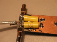
Now, I started the tests with this kind of setup: [the picture is the same, what I attached to one of my previous replys for Thorsten]
That is, two foil capacitors put in parallel, very close to each other, not like in this picture, but really well aligned & touching. The graphs has shown half ESR, ESL decreased by ~ half, with respect to one of the same capacitor. Here I would like to explain, why do I start with this kind of part, and not the config suggested by Thorsten. It's because one can obtain much clearer results by using a film cap: you have a nice neat series resonance point, the capacitance value is more stable with temperature, so any kind of a change in L is promptly visible with these parts.With the electrolytics everything is more difficoult - they are bigger, when you turn them, you involuntarily change lead lenght, the temperature [I solder them on], then there is no resonance, so the result is more vague, if it's not a big difference.
That is, two foil capacitors put in parallel, very close to each other, not like in this picture, but really well aligned & touching. The graphs has shown half ESR, ESL decreased by ~ half, with respect to one of the same capacitor. Here I would like to explain, why do I start with this kind of part, and not the config suggested by Thorsten. It's because one can obtain much clearer results by using a film cap: you have a nice neat series resonance point, the capacitance value is more stable with temperature, so any kind of a change in L is promptly visible with these parts.With the electrolytics everything is more difficoult - they are bigger, when you turn them, you involuntarily change lead lenght, the temperature [I solder them on], then there is no resonance, so the result is more vague, if it's not a big difference.
Attachments
Now, I will positively delude you: I did not enclose a detailed photo reportage about everything: because what I have seen, was very clear.
What I did, was that I swapped polarity of one of the caps in the previous setup. And the resonance point remained exactly the same.
then I repeated with other, different kind of caps: put them in parallel, measured the resonance point, and then swapped polarity on one of them: and there happened nothing, the resonance remained exactly the same.
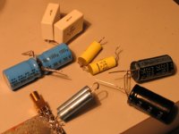
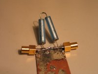
With electrolytics, the picture is not so clear, because of all the reasons of above. To illustrate this, I will include the graph of the configuration suggested by Thorsten, which is visible like the "mirrored" pair of the blu "KoHek" or what it called elcos on this group photo:
What I did, was that I swapped polarity of one of the caps in the previous setup. And the resonance point remained exactly the same.
then I repeated with other, different kind of caps: put them in parallel, measured the resonance point, and then swapped polarity on one of them: and there happened nothing, the resonance remained exactly the same.
With electrolytics, the picture is not so clear, because of all the reasons of above. To illustrate this, I will include the graph of the configuration suggested by Thorsten, which is visible like the "mirrored" pair of the blu "KoHek" or what it called elcos on this group photo:
Attachments
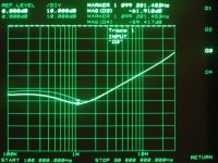
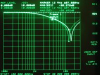
In the graph below, the selected track refers to the config visible on the group pic, that is, the polarity is reversed. the upper track was done in this same "mirror" config, but straight polarity, that is, the pins of the caps facing each other were going like + => +; - => -.
Here you can see my headaches: although the ESL is clearly unchanged, but the ESR was changing nicely - and if I tried it again, I got another ESR values! Bah, electrolytics.. or, something is going on here, who knows?
The same I had tried with the "classic" Super E config setup: two electrolytics side by side, parallel, and then I reversed pins. No change in ESL!
As a special reference to this graph, my humble apologies, you will see strange axis parameters, this is because the traces shown are saved values, and i only noticed later, that I was recalling them in this other setup! The original range for X is from 5 k - to 30 MHz.
Attachments
Here I have to admit, that I expected something like this, somehow I never really believed, that reversing the pins will change the winding direction. You can proove, If you want, that I am wrong.
Also, at this point, it hard to see, what is failing here? winding direction is not changed, or the generated field is not extending out enough to provoke a visible effect in the neighbouring cap?
But, You KNOW, that for example, reversing the CURRENT flowing in the parts close to each other, will cause cancellation - the classic bifilar winding!
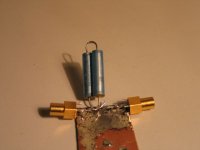
So I tried again, with the following setup:
two film caps, connected in SERIES, [ESR, ESL doubled], and folded back side by side, like this:
Also, at this point, it hard to see, what is failing here? winding direction is not changed, or the generated field is not extending out enough to provoke a visible effect in the neighbouring cap?
But, You KNOW, that for example, reversing the CURRENT flowing in the parts close to each other, will cause cancellation - the classic bifilar winding!
So I tried again, with the following setup:
two film caps, connected in SERIES, [ESR, ESL doubled], and folded back side by side, like this:
Attachments
I have measured this same [series] configuration with all the other caps present on the group pic: the big boxed white Arcotronics show this effect as well as all the others, with one exception, and in a different measure. The most beutiful response I got from these blue, long, thin ERO polyprops. [not without reason..]
What does it mean? For me, it means a lot of things:
If there exists L-cancellation, my setup is sensitive enough to show it.
There EXIST L CANCELLATION in caps close to each other, and not even so infinitely close..
It causes less ESL, to an extent, but obviously does not eliminate it.
Unfortunately, to provoke it, you ned caps in series, which for me eliminates the practical advantage of L - cancellation.
BUT! There is not measurable such an effect, like is described in the Super E config! There I have seen nothing!
Then, I was telling, there was one exception: I could not measure this effect in the electrolytic caps shown here! that is, not measurable L - canc. in caps in series & side by side, like the film types. My hypothesis about it is that the metallic casing cancels out great part of the generated field. That is, I was not able to see anything, except for one case.
Another consequence: a Film cap is unprotected against external fields!
and now I would like to turn back to Thorsten's original setup. As far as I understood, he asked me to measure the " mirrored" two electrolytics config with respect to the classical, parallelled setup.
The "mirrored" config you can see on the group pic, the classic parallel config is here: [so as to clarify]
The "mirrored" config you can see on the group pic, the classic parallel config is here: [so as to clarify]
Attachments
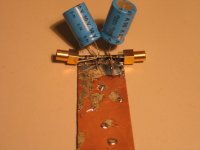
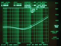
The response, visible here, is the one exception mentioned previously:
Here I see a strong difference. I would like to note, that I tried to use ~ equal lead lenght. I was not really succesful, but I feel that lead lenght in itself does not explain this difference.
Let's clarify again, here I am measuring the [possible] difference between two setup:
The trace selected [highlighted] is THE CLASSIC PARALLEL!
the second trace is the "mirror" config!
I have tried it again & again, there are minor shifts due to all the problems already described, but it basically remains the same: the resulting net L is greater in the "mirror" case!
Here I see a strong difference. I would like to note, that I tried to use ~ equal lead lenght. I was not really succesful, but I feel that lead lenght in itself does not explain this difference.
Let's clarify again, here I am measuring the [possible] difference between two setup:
- Classic parallelled
- "mirror" parallelled, a' la Thorsten
The trace selected [highlighted] is THE CLASSIC PARALLEL!
the second trace is the "mirror" config!
I have tried it again & again, there are minor shifts due to all the problems already described, but it basically remains the same: the resulting net L is greater in the "mirror" case!
Attachments
- Status
- Not open for further replies.
- Home
- Amplifiers
- Chip Amps
- Carlos' snubberized Gainclone Power supply