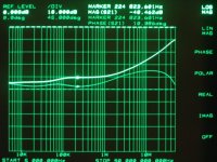
In the previous pic the marker was set at F3. from this I see here .125 ohm ESR and ~93 nH ESL. Strange.
Finally, this would be my trial at this problem:
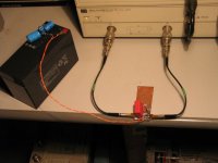
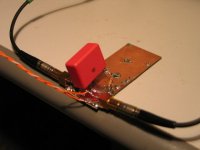
The wima is that "infamous" 4,7 uF Mks 4 like in the earlier setup.
It has in series with it .33 ohm to the ground. The caps on the battery are the decoupler [later on I realized, that for low inductance it's enough / better to use less, but their impedance remained basically the same]
Finally, this would be my trial at this problem:
The wima is that "infamous" 4,7 uF Mks 4 like in the earlier setup.
It has in series with it .33 ohm to the ground. The caps on the battery are the decoupler [later on I realized, that for low inductance it's enough / better to use less, but their impedance remained basically the same]
Attachments
Geez...
Some 20 e-mails on my PM, all from this thread.
Hard to keep up...
For a change, it's good to see an e-mail with this subject:
"Codeine, Viagra, Soma, Xanax, ...."

Some 20 e-mails on my PM, all from this thread.
Hard to keep up...
For a change, it's good to see an e-mail with this subject:
"Codeine, Viagra, Soma, Xanax, ...."
Carlos, excuse me, I did not want to congest the forum, but up to now I did not find out how to put it alll together & more compact!
Upupa, was that question aimed at me?
ciao!
Upupa, was that question aimed at me?
ciao!
Carlos, don't tell us that you need Viagra !?  hehehehe
Xanax, I understand 😉 It was a long way ( 2 threads ) with intense discution 😀 and some times with personal attacks
hehehehe Xanax, I understand 😉 It was a long way ( 2 threads ) with intense discution 😀 and some times with personal attacks
Joseph K said:Carlos, excuse me, I did not want to congest the forum, but up to now I did not find out how to put it alll together & more compact!
Go on, you're doing fine.
Thanks for your work.😎
Konnichiwa,
And what's the bottom line?
Battery & bypass as I suggest keep the overall rail impedance rather low and phase-swings are much less drastic than previously, perhaps more important, in the 100KHz->1MHz region where most os the stability problems seem to happen with an LM3875 the impedance is the lowest of any other setup. It probably is still not ideal, which rigerous analysis shows, but in general pretty well behaved.
I am not quite certain if your analyser keeps always the same attenuation/impedance as reference (wherever that may be), can you confirm that the basis in terms of level/impedance is always the same in all measured options?
Anyway, what do you think, will it work well enough?
Past that, yes we can add resistance in series, probably even as little as around 0.1 Ohm should do the trick. Actually, at a guess, if we have a normal connector the connection resistance is probably suffice to bump up things to a sufficient level. I used an external large "Batt-Pack" (Holy battery batman, that Amp has some mean bass) usually with XLR connectors and coax wiring (usually RG223 because I kept it around.
Anyway, some really interesting stuff there, many thanks for doing the measurements.
Sayonara
Joseph K said:And the impedance: Thanks for Your attention!
And what's the bottom line?
Battery & bypass as I suggest keep the overall rail impedance rather low and phase-swings are much less drastic than previously, perhaps more important, in the 100KHz->1MHz region where most os the stability problems seem to happen with an LM3875 the impedance is the lowest of any other setup. It probably is still not ideal, which rigerous analysis shows, but in general pretty well behaved.
I am not quite certain if your analyser keeps always the same attenuation/impedance as reference (wherever that may be), can you confirm that the basis in terms of level/impedance is always the same in all measured options?
Anyway, what do you think, will it work well enough?
Past that, yes we can add resistance in series, probably even as little as around 0.1 Ohm should do the trick. Actually, at a guess, if we have a normal connector the connection resistance is probably suffice to bump up things to a sufficient level. I used an external large "Batt-Pack" (Holy battery batman, that Amp has some mean bass) usually with XLR connectors and coax wiring (usually RG223 because I kept it around.
Anyway, some really interesting stuff there, many thanks for doing the measurements.
Sayonara
moving_electron said:An intellectual discussion of "why should this be so" or "I don't see how that can be the case since..." is an excellent way to move the knowledge forward
While I certainly agree that this is a worthwhile discussion and no slight is meant in particular to Joseph K who's made a great deal of effort to enlighten us, it isn't anything new.
The turnover of people on forums and failure to use a search engine or read a book means that these discussions and "discoveries" occur over and over again. Progress is not made by reinventing the wheel.
Dear Thorsten!
The bottom line, from my part wanted to be, as You guessed it well, that trading in some ESR of the applied bypass capacitors will pay back in the much better phase response, where it matters. And that resistor between the cap and the ground will transform your good quality film bypass cap from a "histerical primadonna" into a trustworthy old workhorse!
Where it is, where You have doubts about the reference level? The signal level, which by itself does not matter at the end, is written always on the screen. This is a 50 ohm char. impedance line, and this is our reference level, as I explained at the beginning, [that is, 25 ohm].
Because it is the hardware, it's fixed.
An example: in the last diagram, I put that .33 ohm to ground. The calculator tells me it's -38.4 dB down from 25 ohm. you see -40 dB
on the screen just below 1 MHz, which is our new "ESR" for the Wima.
Now, that .33 comes from three pieces of 1 ohm, and I did not measure it, so for me it can well be - 40 dB.
Bottom line - I feel it is rock solid, even over time, this analyzer!
The battery surprised me, also me I would have expected a much larger self inductance!
And the real bottom line is that, again, I would like to thank You for your continous, and refreshing input to this community!
Ciao, and good night! george
Konnichiwa,
Actually, I forgot something. In my case the actual supply has not 1 Battery but 4 in series and bigger ones as well. This would suggest a self inductance for the bypassed stack to be around 0.4uH with around 0.4R "ESR".
If I put that through P-Spice (which matched your earlier measurements quite closely), it suggests in fact a flat impedance curve to around 100Khz and falling impedance from there to whatever the capacitors resonance is, the impedance then climbing back up to reach the 0.4R somewhere around 50MHz.
Now the real question is to determine if a minimum inductance (cap directly at the LM3875 Leads with absolutely minumum lead length) is preferable to increasing the loop area by adding a resistor or not.
Thoughts?
Sayonara
Kuei Yang Wang said:And what's the bottom line?
Actually, I forgot something. In my case the actual supply has not 1 Battery but 4 in series and bigger ones as well. This would suggest a self inductance for the bypassed stack to be around 0.4uH with around 0.4R "ESR".
If I put that through P-Spice (which matched your earlier measurements quite closely), it suggests in fact a flat impedance curve to around 100Khz and falling impedance from there to whatever the capacitors resonance is, the impedance then climbing back up to reach the 0.4R somewhere around 50MHz.
Now the real question is to determine if a minimum inductance (cap directly at the LM3875 Leads with absolutely minumum lead length) is preferable to increasing the loop area by adding a resistor or not.
Thoughts?
Sayonara
Kuei Yang Wang said:Now the real question is to determine if a minimum inductance (cap directly at the LM3875 Leads with absolutely minumum lead length) is preferable to increasing the loop area by adding a resistor or not.
Thoughts?
Sayonara
Kuei, why not use a 2.2uf cap + resistor on the batteries and 2.2uf on the chip's pins?
Dear Thorsten!
My gut feeling is, and this is just a quick response, that the damping positively should take place between power pin and the ground. I think that just the fact of using a film cap for bypassing, instead of a ceramic one, for example, is greatly increasing the local loop area. But You are right, and this is a problem to be resolved yet also for me, to find a good, little compact low value, say 0.1 - 0.3 ohm, resistor for this.
I would look into bigger smd resistors, or use 1/4 watt types, .6 watt types. There is no power flowing into that part.
Ti saluto, george
Joseph,
Yep, my thoughts exactly. What we actually need are super low inductance capacitors with a buikd in well defined ESR to match common electrolytic capacitors and the like, with the kind of foil leadouts on the Wima Snubbers. Now THAT would be a fun part.
Sayonara
Joseph K said:My gut feeling is, and this is just a quick response, that the damping positively should take place between power pin and the ground. I think that just the fact of using a film cap for bypassing, instead of a ceramic one, for example, is greatly increasing the local loop area. But You are right, and this is a problem to be resolved yet also for me, to find a good, little compact low value, say 0.1 - 0.3 ohm, resistor for this.
Yep, my thoughts exactly. What we actually need are super low inductance capacitors with a buikd in well defined ESR to match common electrolytic capacitors and the like, with the kind of foil leadouts on the Wima Snubbers. Now THAT would be a fun part.
Sayonara
Jeff!
I know that they knew it all along!
originally posted by Jan Didden
Sorry? Did I comment on snubbers? I'm not aware of that, I think it is an interesting subject, and I learned quite a lot from Joseph's measurements. In fact I used snubbers on my power supplies, described in the article series I did with with WJ and Gary Galo in Audio Amateur in the mid 90'ies. I'm not sure they were actually included in the articles, (too lazy to look it up now), but I think I did at least discuss the advantage of using lossy capacitors (relatively large ESR, which comes out to the same but is cheaper) to damp the oscillations.
I know that they knew it all along!
AND NOW FOR SOMETHING COMPLETELY DIFFERENT
Jospeh,
Given that you have that cute analyser handy, could I talk you into investigating the "super E cap" configuration?
In case you are unaware, Black Gate have an arrangement where they put two specific types of non polarised capacitors in parallel with the leadouts to each other. What this does (obviously) is to reverse the direction of winding of one of the capacitors and if the axis is well aligned the inductance should be reduced.
Now this should work equally in my view for normal capacitors I should think.
I'd be interested to see what happens (if you don't mind the time) if you put capacitors that way, one for 2pcs in series and two 2pcs in parallel. I don't thin it should be neccesary to reverse the polarities BG claims is needed, but I really don't know. Might be interesting to find out. If we can significantly reduce the ESL in electrlytics by mechanical layout, maybe we don't need no sintinkin snubbers, bypasses and all that jazz?
Sayonara
Oops, Thorsten, my previous post referred to your previous post..
I've told it here already, I would be very happy to put a BG super esl config under torture! I don't have them, yet. Not that I would believe in that, but maybe, if we all, together, publicly would face them with my poor, simple analyser, and they should stand up, instead of Gigaherz regions, to a very plain, common, grey little 200 MHz, and, shhh... eventually ...shhh... would fail... that would debunk a bit this story...
So, as you see, in my opinion there is no easy way out. But, if we can stabilize a reasonable measurement setup, I can put some caps in different configurations in parallel. I have just done that, today, and I got lower ESR and ~ half as much ESL...
now, if you forgive me, I would head for bead...
good night, george.
Joseph,
I'm not so much interested in investing BG's especially (I have some here, I'll dig around), but to see what we can do with normal Caps.
Yup. But could we try the capacitors like this:
(Sorry for the crappy piccie, my digicam is busted....)
In one case it might be interesting to find out what happens to ESL if we have the capacitors like that and once in series with the correct polarity for DC and the other parallel with the correct polarity for DC.
If any "L-cancelling" is possible this configuration should show it, as it results in clockwise/anticlockwise turns on the same axis (hence alignment would be fairly critical).
I don't expect anything, but if could measure reliably that high up I would have long checked it.
Good night....
Sayonara
I'm not so much interested in investing BG's especially (I have some here, I'll dig around), but to see what we can do with normal Caps.
Joseph K said:But, if we can stabilize a reasonable measurement setup, I can put some caps in different configurations in parallel. I have just done that, today, and I got lower ESR and ~ half as much ESL...
Yup. But could we try the capacitors like this:
An externally hosted image should be here but it was not working when we last tested it.
(Sorry for the crappy piccie, my digicam is busted....)
In one case it might be interesting to find out what happens to ESL if we have the capacitors like that and once in series with the correct polarity for DC and the other parallel with the correct polarity for DC.
If any "L-cancelling" is possible this configuration should show it, as it results in clockwise/anticlockwise turns on the same axis (hence alignment would be fairly critical).
I don't expect anything, but if could measure reliably that high up I would have long checked it.
Joseph K said:now, if you forgive me, I would head for bead...
good night, george.
Good night....
Sayonara
- Status
- Not open for further replies.
- Home
- Amplifiers
- Chip Amps
- Carlos' snubberized Gainclone Power supply