pinkmouse said:Guys, stop it now.
Since we can't stop them, i've split the thread -- for those who wish to continue the heated discussion it is over here....
http://www.diyaudio.com/forums/showthread.php?s=&threadid=50555
diyAudio Forums - more objective vrs subjective (from snubberized GC PS thread)
dave

curva said:I decided to change two of them adding the s and then listened again. The difference was there right from the beginning, and time gone since, just added some more of it. For the better, believe it or not
That's right.
It's so obvious that even a blind [pun intended] could hear the difference.😎
My hunt for parts locally ended in disappointment. 🙁 Guess digikey will have to make a delivery soon!
C
C
being encouraged..
by the nice words [thank's to you all] i would like to finish this new little chapter of E-101..
First of all, I have made a mistake, again. In that last measurement
with the MUR860 diodes.
Not in the measurement, but it's interpretation. [you should always watch my hands closely, I'm cheating!]
Inpost 531 we have seen the "pulse" produced. If you take a look, you see it's a sharp front followed by a relatively slow decay. Now this decay worried me, I didn't learn about it in school..
A fast diode does not do this, normally. Now, that decay, it's Tau is about between 20 -30 usecs, as we have ~30usec/division.
So, I have admitted at the beginning, I am using the sniffer C-R, I must, if I want to synchronize on the small pulses. It's 10 nF; 2kohm.
Now, what Tau it would have? khm, not 20 usecs, by accident?
If I would have taken the pic of the full wave, I could have avoided this trouble. But, with such a small "blink" in the 75 Volts p-p full waveform, I simply just could not get a stable pic for the camera.
So, now I went for the heavy arms, and reached for the TDS 620.
I should have done it right at the beginning, but I LOVE analogic!
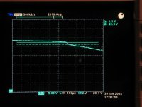
Here it is, it's not a pulse, but a step! This is a common phenomena for all rectified waveforms, but I have to admit, I'm at a loss in explaining. The step voltage is suspiciously close to the diode forward voltage drop under these conditions [~1.5 amps]. I have a vague idea, but do not want to humiliate myself any further.. Please, help me out!
So, the MUR860 does not produce ANY visible reverse recovery snap, but still there is the step at the recharge current cutoff point, which is common for all diodes.
What you see on the pic is the final part of the "plateau", then the small step, then the "sinus" continues.
by the nice words [thank's to you all] i would like to finish this new little chapter of E-101..
First of all, I have made a mistake, again. In that last measurement
with the MUR860 diodes.
Not in the measurement, but it's interpretation. [you should always watch my hands closely, I'm cheating!]
Inpost 531 we have seen the "pulse" produced. If you take a look, you see it's a sharp front followed by a relatively slow decay. Now this decay worried me, I didn't learn about it in school..
A fast diode does not do this, normally. Now, that decay, it's Tau is about between 20 -30 usecs, as we have ~30usec/division.
So, I have admitted at the beginning, I am using the sniffer C-R, I must, if I want to synchronize on the small pulses. It's 10 nF; 2kohm.
Now, what Tau it would have? khm, not 20 usecs, by accident?
If I would have taken the pic of the full wave, I could have avoided this trouble. But, with such a small "blink" in the 75 Volts p-p full waveform, I simply just could not get a stable pic for the camera.
So, now I went for the heavy arms, and reached for the TDS 620.
I should have done it right at the beginning, but I LOVE analogic!
Here it is, it's not a pulse, but a step! This is a common phenomena for all rectified waveforms, but I have to admit, I'm at a loss in explaining. The step voltage is suspiciously close to the diode forward voltage drop under these conditions [~1.5 amps]. I have a vague idea, but do not want to humiliate myself any further.. Please, help me out!
So, the MUR860 does not produce ANY visible reverse recovery snap, but still there is the step at the recharge current cutoff point, which is common for all diodes.
What you see on the pic is the final part of the "plateau", then the small step, then the "sinus" continues.
Attachments
So, I went back and repeated again.
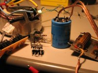
the setup is: transformer 2*24 V AC, - I using only one coil;
a 20000 uF capacitor; 20 ohm load, which produces ~ 1.5 A load.
The rectifiers are interchanged, & always sniffed with the same R -C, 10 nF / 2 kohm. So if you see the slowly decaying tail, it means the diode produced NO reverse rec. pulse "snap", just a step. If, instead, there has been a real pulse, then we will see no decay in the tail - the pulse trailing edge eliminates it. The ringing is real, and is visible after the front of the pulse, if it's a step, or later, if it's a pulse. And, the ringing with this transformer is small & well damped. And probably it will be so for the majority of toroidals, at low voltages. HT EI transformers are another league..
This is the setup, with all the contenders.
Attachments
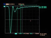
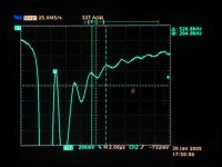
First, the KSL KBPC 2506, again.
I know, I'm cheating, but believe me, I had put the marker on the neighbouring peaks in the train - then stopped the run, and it came like this.. we do not see the step here, together with that, the peak value will be close to ~ 10 Volts. The resonance freq. seems to be at around 500 kHz, which means, the stray cap. & leakage inductance are low in this transformer.
I know, I'm cheating, but believe me, I had put the marker on the neighbouring peaks in the train - then stopped the run, and it came like this.. we do not see the step here, together with that, the peak value will be close to ~ 10 Volts. The resonance freq. seems to be at around 500 kHz, which means, the stray cap. & leakage inductance are low in this transformer.
Attachments
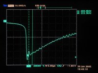
Now, the MUR860, like I tested already before, only now it is a better pic:
Hm, the resonance value seems to be a bit higher - I think that at this low stray secondary capacitance level the diodes reverse capacitance is having a word, as well. Which is now less.
Hm, the resonance value seems to be a bit higher - I think that at this low stray secondary capacitance level the diodes reverse capacitance is having a word, as well. Which is now less.
Attachments

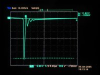
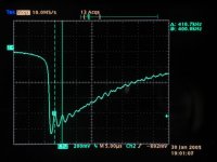
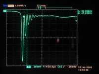
And the MBR760, 7.5 amps /60 volts schottky. Fortunately, there are two in series in the bridge..
What I see, is that the front is sharper, the [forward drop?] step is larger, and the resonance is at around 400 kHz, reverse capacitance values definitely larger then before? The ringing though seems to be less.
What I see, is that the front is sharper, the [forward drop?] step is larger, and the resonance is at around 400 kHz, reverse capacitance values definitely larger then before? The ringing though seems to be less.
Attachments
What I did now, was to put a capacitor across the filter cap, 440 nF // with the 20000 uF. I wanted to see, not only on the analyser, but also on the scope, what difference it might cause on the tank circuit Before the diodes! To enhance the - possible - effect, I've put not a snubber, but directly a cap.
What I see in respect to the previous pic, that the ringing is more emphasized, and it's frequency is a tad higher - strange, I would have expected less. I changed the less possible in the setup - just soldered in place the bypass cap, not moving the parts. Still, I would say, it is a slight difference, if I would translate to nanofarads locally applied, It's a fraction of a nF.
Do not forget, at this very phase the diodes are not conducting, the impedance changes at the filter cap side are arriving here filtered by the diodes reverse capacitance, in the range of a nF or less.
Attachments
Joseph -- why not email Ed Dell of AudioXpress and get your results published -- it would be a good addendum to Hagerman's article from 1994. Email me privately if you care. Jack
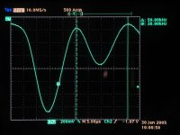
here below it's in a better scale.
Now, at this moment we have enough data to try to define the transformer parameters.
With these same diodes, the resonance peaks at about Fr1=400 kHz.
With Cnew= 100 nF attached, the resonance is Fr2=50 KHz.
Cstray= Cnew / [[Fr1/ Fr2]square -1]
that is, 1.6 nF.
From here, L leak = ~100 uH. It seems to be reasonable, given the high resonance freq. [I am looking at ONE secondary]
I don't have our LCR meter here - tomorrow might try it, but the above method is just another way of doing it.
Attachments
If you look at the front slewing rate before and after the 100nF added, you see why it is a good way of decreasing the emitted noise: from ~ 1volts/usec it is decreased to < .2volts/usec, which means five times less bandwidth in the produced spectrum.
So, I would conclude here - for me this all means, that we have one problem less - though Carlos's snubber is not effective at this point, with these kind of transformers & diodes it is also not needed, to rigorously apply the classic snubbing method.
Ciao, George
So, I would conclude here - for me this all means, that we have one problem less - though Carlos's snubber is not effective at this point, with these kind of transformers & diodes it is also not needed, to rigorously apply the classic snubbing method.
Ciao, George
Something inportant came to my mind: for the italians here, and only in case if they wouldn't remember, a very good source of information is the series of articles of Francesco Callegari in CHF 38; 39; 40; 45.
Lui ci si capisce bene queste cose.
ciao, George
Lui ci si capisce bene queste cose.
ciao, George
- Status
- Not open for further replies.
- Home
- Amplifiers
- Chip Amps
- Carlos' snubberized Gainclone Power supply