In the Right one :There are 4 output pins per each 14 pin op-amp. You need to post the pin number and the voltage.
PINS Voltage
1. 0
2. 0
3. 0
4. +16
5. 0
6. 0
7. 0
8. -13.94
9. -3.40
10. 0
11. -15.75
12. 0
13. -3.37
14. -13.95
MIDDLE ONE:
Pins Voltage
1. -14
2. -6.80
3. -13.88
4. -13.88
5. -13.35
6. -10.94
7. -14
8. -13.32
9. -13.32
10. 0
11. -15.75
12. 0
13. -13.33
14. -13.32
LEFT SMALL ONE:
Pins Voltage
1. -13.12
2. -2.48
3. -11.84
4. -15.78
5. -13.88
6. -13.15
7. -11.95
8. 0
yes,it is an old photo.Is that an old photo? I see the fixative on some components.
In the Right one Output Voltage:
PINS Voltage
1. 0
7. 0
8. -13.94
14. -13.95
MIDDLE ONE Output V:
Pins Voltage
1. -14
7. -14
8. -13.32
14. -13.32
LEFT SMALL ONE Output V:
Pins Voltage
1. -13.12
7. -11.95
PINS Voltage
1. 0
7. 0
8. -13.94
14. -13.95
MIDDLE ONE Output V:
Pins Voltage
1. -14
7. -14
8. -13.32
14. -13.32
LEFT SMALL ONE Output V:
Pins Voltage
1. -13.12
7. -11.95
May be i am checking the voltage with one terminal grounded and second terminal on pins with multimeter.You don't have positive supply voltage on two of the ICs. Why?
Tell me if i am wrong.
30V In the right side and 0.25V in the Middle one and 0.25V in the left side's small op-amp.With a meter, black on pin 11, red on pin 4, what is the DC voltage?
If you got that wrong, all the rest are unreliable. Place the black meter probe on one of the non-bridging speaker terminals and repost the voltages. Do it on the 14 pin op-amp on the right of the photo first. Copy and paste:
Pin 1:
Pin 2:
Pin 3:
Pin 4:
Pin 5:
Pin 6:
Pin 7:
Pin 8:
Pin 9:
Pin 10:
Pin 11:
Pin 12:
Pin 13:
Pin 14:
Pin 1:
Pin 2:
Pin 3:
Pin 4:
Pin 5:
Pin 6:
Pin 7:
Pin 8:
Pin 9:
Pin 10:
Pin 11:
Pin 12:
Pin 13:
Pin 14:
Please can you clarify what do you mean by non-bridging speaker terminals by using or marking in this photo.the non-bridging speaker terminals
Attachments
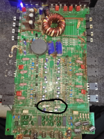
For bridgeable amplifiers, half of the terminals will be used for bridging. The rest (non-bridging) will all be connected directly together and to the secondary ground. That's what you need for the reference (black probe).
Pin 1: 0
Pin 2: 0
Pin 3: 0
Pin 4: +16
Pin 5: 0
Pin 6: 0
Pin 7: 0
Pin 8: -13.94
Pin 9: -3.40
Pin 10: 0
Pin 11: -15.75
Pin 12: 0
Pin 13: -3.37
Pin 14: -13.45
Pin 2: 0
Pin 3: 0
Pin 4: +16
Pin 5: 0
Pin 6: 0
Pin 7: 0
Pin 8: -13.94
Pin 9: -3.40
Pin 10: 0
Pin 11: -15.75
Pin 12: 0
Pin 13: -3.37
Pin 14: -13.45
Hello Bro
I am Really Sorry for Leaving this thread in half.
Actually i sent this amp to local repairing shop but unfortunately they also can’t fix it.
Please help me
Problem : left side channel IC mosfet is overheating after just giving the power.
Reason : There is no earthing in the wires in my house, so when I was using my PC, the amplifier was connected through cable, and I was checking something in the amp, but then the upper plate of the amp touched the amp circuit and something got short circuited, and then this problem started. Before this it was not working without removing the 2 audio ICs, only the right side channels were working.But it all started from the bass on off button in bottom left corner, at that time i was not perfect in iron solidering but i tried to change the damaged button by myself but it results in damage the prints of that button area.
Please replyAre all of the potentiometers in good working order?
Is the preamp board plugged in?
.Problem : left side channel IC mosfet is overheating after just giving the power.
If you bridge the bias transistor base to collector, do they still heat up?
Be prepared to disconnect power in case draws excessive current.
Be prepared to disconnect power in case draws excessive current.
- Home
- General Interest
- Car Audio
- Car Amplifier have power but no sound. Please help me