to my eyes this looks like much better performance overall, and much greater attenuation out at the MHz levels, by simulation - in practice it may not drop as much going up into the MHz.
(it's just a quick approximation, not in any way optimized or calculated)
(it's just a quick approximation, not in any way optimized or calculated)
Attachments
I congratulate you on your success. Did you use perfect capacitors and got the ideal effect. 🙂 We only have to buy the capacitors without ESL and ESR. Seriously, you deleted the capacitors had these important parameters, but the newly installed C6 and C20 - no.to my eyes this looks like much better performance overall, and much greater attenuation out at the MHz levels, by simulation - in practice it may not drop as much going up into the MHz.
(it's just a quick approximation, not in any way optimized or calculated)
Attachments

Last edited:
sure go ahead and add some ESR and ESL...
I deleted none of the parts in your file. There were some open "wires".
(I think I got a 'read error' on opening, so that might be the problem with "deleted components".
Not sure why there was such an error...)
But the complex network you put in is not exactly the conversation that was going on last... the topic shifted a bit to the issue of what happens when there is a big current draw and how does the charging waveform for the caps look?
And anyhow there is some question as to IF the HF shunt type filter network you showed will do much placed back at the PS, and if perhaps it needs to be closer to the devices needing the filtering... and of course, what is the source of this HF that needs the filtering out in the MHz region?
I'd suggest that for people who happen to live somewhere near a 50kW (the max now in the USA for standard broadcast) AM tranmitter, that "it's in the air".
And also for an amp with a power bandwidth of <200kHz (which is the vast majority) what if anything will some uV of RF do that needs treatment? Is it a problem?
Last edited:
3-4nH is a much more realistic inductance for the 1u caps. For through-hole parts anyway, maybe you meant SMD...
100mH 10A chokes are too expensive.
I think it's closed-core and gapped-core inductors that don't radiate much. If the core does not complete a loop around the coil, then it isn't much different from the radiation of the same coil without the core (assuming current through the inductor is the same).
gapped ferrite core with the coil covering the gap is the lowest EMI, If there's no gap visible this is a powdered iron core (with a distributed gap ).
then a closed magnetic structure helps. I believe the OPs core is powdered iron > a compromise for lowest cost and better EMI than a toroid structure.
then a closed magnetic structure helps. I believe the OPs core is powdered iron > a compromise for lowest cost and better EMI than a toroid structure.
and dangerous when the amplifier load is switched dynamically. Current doesn't like to change abruptly in an inductor so they become a instant voltage source.100mH 10A chokes are too expensive.
Last edited:
My thought is to use small value inductor with high SRF to get rid of the RF noise coming from the mains and the rectification process. Since the amplifier's PSRR is poor at RF, rail RF noise can get into the circuit to modulate with the signal and get into the feedback path via the large capacitance of the output MOSFET devices, for an example.
But it makes no sense to me to employ a large inductor on the rails to deal with noise / ripples below RF because the amp's PSRR at lower frequencies is much better and capacitors can do a better job without numerous other problems of using an inductor.
But it makes no sense to me to employ a large inductor on the rails to deal with noise / ripples below RF because the amp's PSRR at lower frequencies is much better and capacitors can do a better job without numerous other problems of using an inductor.
This is a different problem, and these different problems have different solutions. If you need to get rid of the RF interference, it is necessary to break the power cord ~110 (us - ~220) V, and paste in the gap inphase transformer. The same transformers should be put in cables of the speaker and input cables. We can see sometimes on the cable thickening. This ferrite core is put over the cable and forming with its wires inphase transformer.to get rid of the RF noise coming from the mains and the rectification process.
Interference from the distorted currents charging the capacitors the diodes of rectifier are reduced by the installation of snubber circuits (a circuit Zobel-Bushero) parallel to the diodes of the bridge.
The installation of the inductor in the supply circuit is not effective, neither in the first, nor in the second case.
Last edited:
We usually refer to those a common mode chokes or CMCs. The large ferrite beads are called ferrite cable clamps.
So why put it in the power cord rather than inside the appliance at the power input?
So why put it in the power cord rather than inside the appliance at the power input?
They can be put anywhere. But this problem with RF interference do not quite correspond to the theme and the header.
In my opinion, even if the mains power is clean, after rectification, and even after we put in a snubber, there is still a lot of high frequency noise. The wave forms after rectification are no longer 50Hz or 60Hz sine waves. They are almost triangles! Do a FFT and we can see the composition of the harmonics.
Put a big ferrite core around the power cable won't solve the problem. We need to filter out the higher frequency noise in the rails after rectification before it gets to the amp because no amps have high enough PSRR at higher frequencies.
Put a big ferrite core around the power cable won't solve the problem. We need to filter out the higher frequency noise in the rails after rectification before it gets to the amp because no amps have high enough PSRR at higher frequencies.
First question, what is the "need" that you mention regarding the "higher frequency noise".
What frequencies?
What is the amplitude of said frequencies?
How does that compare to the ambient RF energy from sources including AM broadcast?
And, how will they have any discernible or even measurable effect on the output, which goes to a speaker that has nil response to anything RF...
(I'm not saying to not make things clean, I'm just asking if you are "cleaning" something that is worth cleaning or not)
Just simulated. On a power amp with 3 x 10,000uF computer grade low ESR reservoir capacitance, the rectified triangle wave forms at 100Hz transformed with FFT show 10kHz harmonics at -75dB. OK, 10kHz not quite RF. I have exaggerated it. Would you be happy with -75dB at 10kHz?
in all my experience in EMI and RF, I have found its best to filter or snub HF noise close as you can to the source of it (keeping the loop area small ). RF can easily escape and pop up in other places. Filtering doesn't absorb much of the energy so snubbing is often more effective. There are lossy type ferrites that can used in filters. Powdered iron is generally lossy but doesn't offer high inductance.
Using your ear to tune things is a poor tool to judge circuit design/ effectiveness. Don't try to find solutions to imagined RF problems you may just be creating other real issues instead
Using your ear to tune things is a poor tool to judge circuit design/ effectiveness. Don't try to find solutions to imagined RF problems you may just be creating other real issues instead
Last edited:
Yes, it is.They are almost triangles!
This problem is not so great. Currents harmonics mainly closed through the impedance of the capacitors.Put a big ferrite core around the power cable won't solve the problem. We need to filter out the higher frequency noise in the rails after rectification before it gets to the amp because no amps have high enough PSRR at higher frequencies.
1. These harmonics don't annoy us above 0.15...0.3 ppm, even without special solutions. For example, all these amplifiers have no special snubber circuits. But measurements show very good results.
2. Therefore, the inductors, increase the impedance of capacitors for the rectifier, is not needed.
Snubber circuit for the rectifier a little improve the situation.
Last edited:
in all my experience in EMI and RF, I have found its best to filter or snub HF noise close as you can to the source of it (keeping the loop area small ). RF can easily escape and pop up in other places. Filtering doesn't absorb much of the energy so snubbing is often more effective. There are lossy type ferrites that can used in filters. Powdered iron is generally lossy but doesn't offer high inductance.
Using your ear to tune things is a poor tool to judge circuit design/ effectiveness. Don't try to find solutions to imagined RF problems you may just be creating other real issues instead
I think that is excellent advice. My past limited experiences match what you said. I modified a Blu Ray player that had a SMPS supply that was very noisy. Using LRC filters I had limited success. Using snubbers and ferrite beads gave me better success.
I guess the noise spectrum we experience in audio is from tens of KHz to low tens of MHz. They may come from switch mode power supplies or even linear supplies out of the sharp angle of rectified currents. The noise requires low frequency ferrites rather than high frequency ferrites. I am worried that ferrites would get saturated easily if used in a power amp.
I have played with wrapping around the mains power cord with clip-on ferrites. I was extremely surprised that it did have an effect on my Blu Ray player - not a positive one but a negative one! It created a kind of nasty distortion that made the bass sound very wired. I had two audio friends with me at that time. One of them asked me to remove the clip-on ferrite and when I did the distortion in the bass was gone. That was easy to repeat and we confirmed that finding. Of course, although the perception was bass distortion, I believed it was higher frequency harmonics giving the perception of bass distortion.
I could never understand it. The Blu Ray player had so many layers of filtering, with X2 cap, CMC choke input, then SMPS, then LCR filtering, then 2 more 3-terminal regulators before the analogue board. I could not imagine how a clip-on ferrite on the power cord would have a negative effect.
If the clip-on ferrites were on the power supply wires of a power amp, it would say the distortion could be due to saturation of the ferrites. But on a Blu Ray player? How much current would it draw?
I have gone for University studying science for 7 years (not related to audio or EE though) and I would definitely be in the objective camp. But I feel that audio, while most of the time is science occasionally is some black art.
😀
Last edited:
If you pass a pair of Flow and Return wires through a ferrite bead/ring, then there is no inductive effect and no saturation due to the signal current passing through.
If the pair of wires picks up some common mode interference, then that does see an inductive effect. The higher the frequency of that interference the more the impedance of the inductive effect.
Combining a ferrite very close to the case followed by a capacitor just as the signal enters the case creates a very effective common mode HF filter that does not saturate. Very close could be inside the plug of the input cable.
This common mode filter does not filter the differential mode interference.
Last edited:
Yes, it is.
This problem is not so great. Currents harmonics mainly closed through the impedance of the capacitors.
1. These harmonics don't annoy us above 0.15...0.3 ppm, even without special solutions. For example, all these amplifiers have no special snubber circuits. But measurements show very good results.
2. Therefore, the inductors, increase the impedance of capacitors for the rectifier, is not needed.
Snubber circuit for the rectifier a little improve the situation.
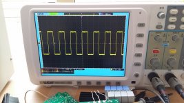
T117, Thanks for joining the conversation. I measured my amplifier a couple of months ago and the measurements look fine. Below was a shot of the image when the amplifier was loaded with 8R and injected 10kHz square waves.
Do the square waves look fine? I guess so. Did the amp sound good? Definitely not. So I followed this thread's advice and reduced some LRs and added more C to the PSU. Each time I added more C, the amplifier sounded better. But I bet if I measured the amp again, the graph of 10k square waves would still pretty much look the same. If I need to find out the real differences, I would probably need to really study EE and get some fancy expensive equipment before I would even dare to try it.
Attachments
If you pass a pair of Flow and Return wires through a ferrite bead/ring, then there is no inductive effect and no saturation due to the signal current passing through.
If the pair of wires picks up some common mode interference, then that does see an inductive effect. The higher the frequency of that interference the more the impedance of the inductive effect.
Combining a ferrite very close to the case followed by a capacitor just as the signal enters the case creates a very effective common mode HF filter that does not saturate. Very close could be inside the plug of the input cable.
This common mode filter does not filter the differential mode interference.
Andrew, good reminder for me to think of it for common mode noise suppression.
I tried it at the input of my preamp. I used a low frequency lossy ferrite ring and wrapped 2 wires around the ring for a couple of turns to approximate a CMC choke. One wire is for signal and the other for ground. The result was mixed. I was not sure if it were better or worse. It definitely changed the sound a bit. I would need to evaluate that again.
So what you are suggesting is that if I wrap around the power wires out of a power amp PSU together with clip-on ferrite, the ferrite should not be saturated and could suppress CM noise on the power supply?
Don't call it ground:
Flow from the Source and RETURN to the Source.
When the two opposite direction currents are identical, then there is no effect from the ferrite.
You don't need to wrap the cable around the ferrite. Just pass it through the hole in the ring/bead.
And keep it VERY CLOSE to the case. Cable after the bead picks up interference.
I check the impedance of the power rails, looking at the shape of the voltage at those busbars during the amplification of the square wave, but not on the output of the amplifier. The shape of the square wave output shows the ability of the amplifier, the waveform on rails - rails opportunities.Do the square waves look fine? I guess so. Did the amp sound good? Definitely not.
P. S. the more times you can wrap wire around a ferrite torus, the more inductance, the better filtering. Buy ferrite toroid and wrap the wire around it 1 time - money down the drain.
- Status
- Not open for further replies.
- Home
- Amplifiers
- Solid State
- Capacitor Array on Power and Ground planes – How to Avoid Resonance?