Ok, I'm currently on night shift. I will make the measurement as soon as I can.power down, R10 temporarily remove from the circuit (no problem for testing) after that check the resistors value R7 and R8 if they are ok, then measure Q1 and Q2 all pins voltages again
thanks
ok these are the readings....the first mpsa29 is E=13VDC B=14.3VDC C=66.0 VDC the 2nd mpsa29 is E=13VDC B=13VDC C=68.0VDC R7=1.27K R8=1.59K R10=9.81K out of circuit.
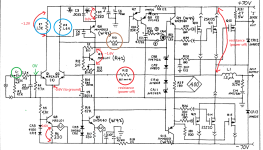
The first mpsa29 B=14.3VDC has problem, pin B voltage must be near 0V, that's why there is a positive DC in the output
There must be something shorted to a 14.3VDC for the input circuit, according to the diagram the C1 capacitor will block any DC input and the Q1 base pin should be near 0V, please check and find out what caused the DC input
There must be something shorted to a 14.3VDC for the input circuit, according to the diagram the C1 capacitor will block any DC input and the Q1 base pin should be near 0V, please check and find out what caused the DC input
Attachments
Last edited:
ok these are the readings....the first mpsa29 is E=13VDC B=14.3VDC C=66.0 VDC the 2nd mpsa29 is E=13VDC B=13VDC C=68.0VDC R7=1.27K R8=1.59K R10=9.81K out of circuit.
ok Patrick, on 1 of the input pairs i do have 0 volts ....the problem is that since this board has no markings it makes it difficult to know Q1 from Q2 ..but yes, one of the mpsa29 i believe this to be Q1 has 0 volts at the base.....once again thanks for all your help. Frank
Ok, all resistor have been reinstalled and Q1 has 0 volts dc at the base,but from Q1 and Q2 emitters to the collector of Q3 ..the reading is 14vdc....what next?
diodes cr3 cr4 and Q3 supply current Q1 Q2how about cr3 diode and cr4...anything to do with it?
now just try replacing Q3 and see

It may be better to restore the circuit to its original form before proceeding. However I would first ask as rayma just did, what was the symptom you were trying to fix that started all this parts changing? Was it simply that you noticed a high voltage at the output? If so, did the amp ever work original configuration. I still haven't found the
This amp was purchased from a person that was honest and told me the amplifier had 1 channel down. I figured it would be an easy fix but I was wrong. All parts have been put back to how it was when I received it. All the semiconductors wher pulled and check with a dvom and a peak advanced tester. ...the problem is that I still have 59volts at the speaker output of 1 channel......the input pairs Q1 and Q2 have the emitters that are tied together and go connected to the collector of Q3 that connection has 14vdc when it shouldn't be.It may be better to restore the circuit to its original form before proceeding. However I would first ask as rayma just did, what was the symptom you were trying to fix that started all this parts changing? Was it simply that you noticed a high voltage at the output? If so, did the amp ever work right?

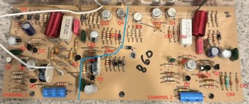
Wow, that labeling is going to help me so much. Thank you. I will post a clear pic of the bottom.
Ok, I was thinking would it be a good or bad idea to swap the mosfets from the working channel ?
it's not a good idea to swap the mosfets yet, try this first
maybe there is oscillation, try increase capacitor C4 at Q6 pin b, C
add two 100p capacitors at Q9, Q12 pin b, C, solder them directly on the bottom PCB of the transistor pins
Last edited:
If there really is a voltage between the emitter of Q1/Q2 and the collector of Q3 the pcb trace between them has to be broken.Ok, all resistor have been reinstalled and Q1 has 0 volts dc at the base,but from Q1 and Q2 emitters to the collector of Q3 ..the reading is 14vdc....what next?
- Home
- Amplifiers
- Solid State
- can anyone offer help understanding the flow of this circuit