Hello, I bought the amp knowing 1 channel wasnt working. 1 channel has 59dc at the output of the speaker leads
Ok, correction. across the 180ohm resistors...I think these are the ones connected to the gates of the mosfets? ...dc volt =0volts. there is a 180ohm resistor for each channel across those resistors i got a reading of 500mv, i think thats the bias?
Wow, I was just about to suggest redrawing the indecipherable spaghetti into something easier to debug.
Ah ok thanks.
Why on earth would the OP open a second thread to continue trying to fix the same amplifier from last year...
thanksr18= 21.9 ...voltage across r17 220ohms =.61volts
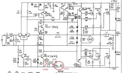
power down, no voltage at the supply rails, measure the output MOSFETs resistance in the circuit board and the feedback resistor R15 (schematic value is 22K), if the resistance is normal then I listed the reference voltages in the diagram for the amp in normal condition, please check and compare with them
Good luck
Attachments
Different amplifierAh ok thanks.
Why on earth would the OP open a second thread to continue trying to fix the same amplifier from last year...
thank you Patrick. I really appreciate the help. the measurement on the Q1andQ2thanks
power down, no voltage at the supply rails, measure the output MOSFETs resistance in the circuit board and the feedback resistor R15 (schematic value is 22K), if the resistance is normal then I listed the reference voltages in the diagram for the amp in normal condition, please check and compare with them
Good luck
thanks
power down, no voltage at the supply rails, measure the output MOSFETs resistance in the circuit board and the feedback resistor R15 (schematic value is 22K), if the resistance is normal then I listed the reference voltages in the diagram for the amp in normal condition, please check and compare with them
Attachments
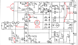
these are the reading i came up with. very hard to do with no numbering on the pc board. ..not sure how to check the resistance of the mosfets but i did check them with a peak tester and all the mosfets were identifiable. the connection from +70 to the 1.2uh coil is open infinite res
Last edited:
OK these MOSFETs pin D and S is not shorted and the feedback resistor is ok
your input diff pair Q1, Q2 emitter pin voltage is no right, maybe failed, you can take it out and test or replace them
your input diff pair Q1, Q2 emitter pin voltage is no right, maybe failed, you can take it out and test or replace them
Last edited:
my marking is all DC voltage, ~ sign mean just around this voltagecorrection,ac volts across Q5 is 0.1volts
ok, changed out the Q1 AND Q2............still have 66.3 vdc at speaker outputs...yes thanks. I thought the sqigley line ment ac volts

Okay the outputs seem okay or at least the gates are not blown and the other 180 ohm voltage seems okay. The suggested voltages would be good to know. The 220uf cap wont be happy after seeing relatively high reverse voltage. Can you Ohm out the Mosfet cases to the heat sink with the power off?Ok, correction. across the 180ohm resistors...I think these are the ones connected to the gates of the mosfets? ...dc volt =0volts. there is a 180ohm resistor for each channel across those resistors i got a reading of 500mv, i think thats the bias?
- Home
- Amplifiers
- Solid State
- can anyone offer help understanding the flow of this circuit