Hi,
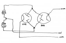
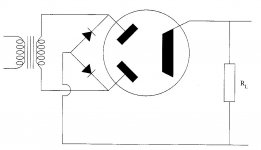
Can 2 twin diodes be used to generate split rails?
Or a hybrid bridge?
The reason I'm asking is that I've been asked to upgrade an active crossover which currently has 2, positive supplies using twin diode rectifiers.
I'd really like to work with split rails because it eliminates components from the crossover filters and removes the need for high voltage capacitors in the crossover filters. I'd also be able to use CCSs in the cathode follower filter stages.
I'd like to retain the tube rectifiers if possible.
Thanks!


Your first diagram can't work because they'd both make identical positive supplies. The second could work just fine. You'll need to design into it a way to split the positive and negative around signal ground. A center tapped secondary like the first diagram is ideal.
All good fortune,
Chris
All good fortune,
Chris
You ideally will need four thermionic diodes, the same way as a normal full wave bridge with a centre tap. You could choose two thermionic diodes half wave bridge with a single winding, grounding one side of the winding and rectify the other both positive and negative.
Using thermionic devices means heaters. A winding for each!
Using thermionic devices means heaters. A winding for each!
Your first diagram can't work because they'd both make identical positive supplies. The second could work just fine. You'll need to design into it a way to split the positive and negative around signal ground. A center tapped secondary like the first diagram is ideal.
Chris
D'oh! If I'd drawn semiconductor diode symbols on my diagram alongside the tube rectifiers that would have been obvious.
The centre-tapped secondary is already part of the existing power supply.
I'll go with the hybrid bridge.
Thanks!
Using thermionic devices means heaters. A winding for each!
Thanks. The heaters and heater windings are already in place.
I'll go with the hybrid bridge.
You need 2 hybrid bridges, 1 for the positive rail and 1 for the negative rail. A bridge gets connected between each end of the rectifier winding and the CT. The CT is not grounded. The O/Ps of the bridges get wired back to back.
The "textbook" setup of a single bridge wired to the rectifier winding's ends and a grounded CT is, in fact, 2X FWCT setups wired back to back. A single hybrid bridge configured in this manner would rectify 1 rail with vacuum diodes and the other with SS diodes. Asymmetry at its worst is definitely not what you want.
more information needed, hard to be guessing on just what you said...
a schematic with psu of your current unit will surely help to give you a more accurate advice...
a schematic with psu of your current unit will surely help to give you a more accurate advice...
more information needed, hard to be guessing on just what you said...
a schematic with psu of your current unit will surely help to give you a more accurate advice...
Here's the existing HT supply. There are 2 of these in each of the left and right power supplies.
BTW, my calculations based on Morgan Jones' book suggest that at 12mA measured through the 1K resistor, the supply isn't pulling enough current through the inductor to allow it to work properly.
Attachments
well you can use two diodes and i mean two separate ones, then just use half of the power traffo secondary and do a full wave voltage doubler...
you can then have your split supply...something like this....
your ground or 0 volt reference the becomes the junction where two caps and the other side of the secondary winding meet...

you can then have your split supply...something like this....
your ground or 0 volt reference the becomes the junction where two caps and the other side of the secondary winding meet...

OK, it's a choke I/P filter and drawing the critical current is important, for good regulation. A reasonable approximation for the critical current, in mA., is given by V/L. Here, the inductance is 15 H. So, a 15 Kohm bleeder resistor of appropriate wattage rating has to be placed across the 1st filter capacitor.
Here's the existing HT supply. There are 2 of these in each of the left and right power supplies.
BTW, my calculations based on Morgan Jones' book suggest that at 12mA measured through the 1K resistor, the supply isn't pulling enough current through the inductor to allow it to work properly.
Do you actually mean there is one of these in each? Never mind - doesn't matter.
At 12mA draw, your critical inductance is about 25Hy, so these existing chokes are best used as filtering.
A full wave bridge, with any type of diodes, will give you about + and - 275 to 300VDC at these modest current demands. Since this makes most efficient use of the transformer, it should be safe to draw 12mA from both + and -.
All good fortune,
Chris
well you can use two diodes and i mean two separate ones, then just use half of the power traffo secondary and do a full wave voltage doubler...
you can then have your split supply...something like this....
your ground or 0 volt reference the becomes the junction where two caps and the other side of the secondary winding meet...

That works, but each rail is 1/2 wave rectified and huge caps. are needed to obtain a satisfactorily low ripple level. The OP wants vacuum rectification and large filter caps. are not feasible.
i have done that, and the caps need not be huge, two chokes, one for each leg is needed this time..
the silicon diodes are replaced with half wave tube rectifiers, each will have its own filament winding supply as the cathodes are connected to the filament supply and so must have good insulation of the side of the power traffo..
what the OP wants to do is doable, but will require a power traffo with several 6 volt filament windings that are insulated for high dc voltage...
two filter chokes, this is doable..
what worried me more is the crossover circuit itself, if they are already wired up....
that will indeed be a lot of work....
if just starting to build then that is fine...
That works, but each rail is 1/2 wave rectified and huge caps. are needed to obtain a satisfactorily low ripple level. The OP wants vacuum rectification and large filter caps. are not feasible.
that is the full wave doubler, if you look closely, secondary winding currents flow for the entire 360 degrees of the the electrical cycle, half wave doublers used only 180 degree of the electrical cycle..
and just as easily implemented with vacuum tube diodes, i posted that drawing just to show concept...
ripple voltage is equal to load current in A, divided by 756 x C where C is in farads, 756 is a constant derived from 6.28 x 120 hz....
For more efficient use of the transformer, put another full wave doubler on the other winding. Then you have a full wave bridge and 120 Hz ripple to both + and - instead of 60 Hz.
All good fotune,
Chris
All good fotune,
Chris
ripple voltage is equal to load current in A, divided by 756 x C where C is in farads, 756 is a constant derived from 6.28 x 120 hz....
With the center of the capacitors grounded, each supply (+ and -) gets 60Hz ripple. It's only 120Hz ripple if the caps are in series across a single supply. Does that make sense?
All good fortune,
Chris
most efficient use of the power transformer happens when the secondary winding is flowing current for the full 360 degrees of the electrical cycle, less heating effects too...
in the case of the full wave center tapped psu, half of the winding conducts currents only on the 180 degrees of each electrical cycle, so half of the time the other half conducts and the other half idles, not so efficient, but in the old days, they had no choice....and they found it convenient with the available tube rectifiers then....
today we have more choices...
With the center of the capacitors grounded, each supply (+ and -) gets 60Hz ripple. It's only 120Hz ripple if the caps are in series across a single supply. Does that make sense?
All good fortune,
Chris
well if you look at the Marantz 9, Citation 2, Pioneer SA-81 and many others, that made sense..
full wave rectification produced 120hz ripple voltage, half wave 60 hz...
i have used full wave voltage doubles in most of my builds because it made sense to me, and since i make/wind my own traffos used in my tube amps, making traffos that have lower secondary winding voltage is not only easy on the insulation, but cheaper and faster to make too..
you should try it too and may even like it.....damper tube diodes can be used here aside from the usual 5u4 like rectifiers...
and by the way, the 0 volt reference can be made using the junction of the filter caps if you wanted a split rail, or at the bottom of the bottom filter cap if want just a single rail....very versatile...
Patrick Turner explains it better....powersupplies
- Home
- Amplifiers
- Tubes / Valves
- Can a pair of twin tube diodes be used to generate split rails?
