There was no problem with the diodes.
After a lot of blown fuses the problem seems to be in using both windings of the centre-tapped transformer this way:

There's no problem if I use one of the secondaries of the second transformer like this:

I don't understand why but would love to know.
Before the fuse blew each time the output voltage would get up to about -5V. Maybe there's some insulation breakdown in the original secondary I was using.
I could try using both windings of the second transformer and see if I have the same problem.
I measured the output voltages at ±145V but the mains voltage is low right now.
Now to have a closer look at post #44.
After a lot of blown fuses the problem seems to be in using both windings of the centre-tapped transformer this way:
There's no problem if I use one of the secondaries of the second transformer like this:
I don't understand why but would love to know.
Before the fuse blew each time the output voltage would get up to about -5V. Maybe there's some insulation breakdown in the original secondary I was using.
I could try using both windings of the second transformer and see if I have the same problem.
I measured the output voltages at ±145V but the mains voltage is low right now.
Now to have a closer look at post #44.
It is bizarre and not easy to understand without being able to 'touch' it... I appears that there is a connection to 'ground' via the transformer centre tap?
Silly question again, with the split primaries, do you still get a negative output if you pull the bottom 6X4 (U2) out?
Be careful until you work out where the connection is/was. Even the scheme in #44 could fail if there is a centre tap to ground resistance...
Silly question again, with the split primaries, do you still get a negative output if you pull the bottom 6X4 (U2) out?
Be careful until you work out where the connection is/was. Even the scheme in #44 could fail if there is a centre tap to ground resistance...
Just a thought, is a grounded 6.3 VAC filament winding present? The 6X4 heaters really should be on separate, dedicated, windings (1 winding per rectifier bottle).
I see a short as follows- When the top end of L2 is negative D1 is set to conduct. At the same time at the opposite and of the PT the potential has gone +ve so pins 1-7 of U2 will conduct thru to the CT of D1 & D2. A good path for lots of current.
If the fuse doesn't blow an alternate path appears in a similar way during the nexr half cycle of the supply.🙂
Am I missing something??
If the fuse doesn't blow an alternate path appears in a similar way during the nexr half cycle of the supply.🙂
Am I missing something??
Just a thought, is a grounded 6.3 VAC filament winding present? The 6X4 heaters really should be on separate, dedicated, windings (1 winding per rectifier bottle).
The 6X4 heaters are indeed on separate 6.3VAC windings - one on each of the power transformers.
It does look that way but this is a standard configuration.I see a short as follows- When the top end of L2 is negative D1 is set to conduct. At the same time at the opposite and of the PT the potential has gone +ve so pins 1-7 of U2 will conduct thru to the CT of D1 & D2. A good path for lots of current.
If the fuse doesn't blow an alternate path appears in a similar way during the nexr half cycle of the supply.🙂
Am I missing something??
Attachments
Your drawing using a common centre tap. The circuit you posted just now uses two separate windings. Perhaps that's the problem?
I see a short as follows- When the top end of L2 is negative D1 is set to conduct. At the same time at the opposite and of the PT the potential has gone +ve so pins 1-7 of U2 will conduct thru to the CT of D1 & D2. A good path for lots of current.
If the fuse doesn't blow an alternate path appears in a similar way during the nexr half cycle of the supply.🙂
Am I missing something??
DOH!
You are correct, that's the problem. The centre tap shorts the two sections. You can only use that configuration with 2 independent secondaries...
A fresh pair of eyes!
Last edited:
The Simple Solution
Why not just connect one of the 6X4s as an ordinary FW rectifier for the +ve supply. The -ve thru a pair of SS diodes, so FW, then the other 6X4 to hold off the -ve until the +ve is ready? Looks like that satifies all the requirements of the cct.
Without complication. Two 6V heater supplies required.🙂
Active Crossover PS Conversion
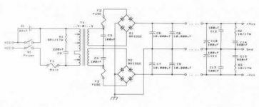
Looking at the schema of the original PS I see no problem at converting to nominally equal +ve & -ve rails of essentially the same potential as I previously pointed out. Looks like 250V at the output to the load, what is the load current? Is the original really connected choke input? That is not required at all, your application is for active crossover networks that are using operational amps of some sort. So all is running Class A, doesn't need the better regulation of a choke in rectifier filter.
And 220 microF caps? Doesn't make sense in an old toob type cct. The 6X4 specs say 10 microF max for cap in filter. Something to be aware of. Also keep in mind that it is the RMS currents that cook PTs, not the average. Large filter caps push the cct over the side pretty quick.
Over time I've built many Op Amps with toobz but in those cases I always used regulated rails in order to avoid DC drift of the output. Your app can probably run without that refinement.
So here are some potential problems to look at. The H-K insulation of most tubes max's out at about 200V. So putting a limit on the -ve rail is always good insurance. That can be done with either a single VR tube or some Zeners, both with a suitable current limiting cct.
For appearance the 150V 0A2 would look good, same envelope as the 6X4. In general the -ve rail in the OP Amp World does not need as much current as the +ve rail. That means a couple of RC networks would be more than sufficient to get the hum on the -ve rail in order. At the VR terminals you should see microvolts. To eliminate any grass on the trace a 0.01 microF ceramic works well. Much larger & you will have a pretty good oscillator.
If you use zener(s), better to use two or three rather than a single Zener. The voltage across an operating Zener is very temperature dependant, that seems to be more with higher voltage. The lower voltage Zeners also have lower dynamic resistance than the higher voltage versions. So better performance is got by using say three 50 Zeners than a single 150V Zener. the leads need to be free to dissipate heat as well. don't cover them with sleeving. If on a PCB leave some lead free to dump the heat. And a 0.01 microF ceramic cap will clean up any stray noise.🙂
Attachments
Your drawing using a common centre tap. The circuit you posted just now uses two separate windings. Perhaps that's the problem?
Thanks very much for noticing that!
Looks like 250V at the output to the load, what is the load current?
Is the original really connected choke input?
With this project it's always been a dilemma as to what to change and what to leave unchanged. My original brief was just to change the 4-way crossover frequencies but there were so many problems (including safety issues) with the original design and implementation it's gone way beyond that.
I could just give you a figure for the load current but at the risk of complicating matters I'll include a bit more information. Part of the reason this has gone on so long was that I didn't provide sufficient information at the beginning.
The original 2 CLC filter power supplies, each of which looked like this:

each supplied 2 common cathode gain stages and 3 cathode follower filter stages for a total of approximately 10mA.
Incidentally, each mains transformer has a 12.6V winding which is rectified, filtered and regulated to supply the heaters of 3 12AX7s.
The original unipolar design was suffering 20dB of attenuation due to the use of low value cathode follower bias resistors. It appears that the gain stages are there to restore the lost 20dB.
My plan is to switch to a single split rail supply, eliminate the bias resistors and do away with the gain stages.
So, in summary, load current of the new split-rail supply will be 6 cathode followers or approximately 12mA.
And 220 microF caps? Doesn't make sense in an old toob type cct. The 6X4 specs say 10uF max for cap in filter.
That would explain the 10uF capacitor at the output of the VRs in the original 250V supplies. My plan is to replace those with much smaller capacitors for switching transient filtering only to reduce the output voltage to 0.9Vin.
The 220uF caps are all glued into place so I might as well use them. There are an additional couple at the end of the umbilicals in the filter boxes. So, total of 3 220uF caps on each 250V supply.
With the 6 10,000uF caps on the 12.6V heater supplies (3 on each) it's no wonder a 5A fuse is needed to withstand the switch-on surge.
...regulated rails in order to avoid DC drift of the output. Your app can probably run without that refinement.
With the variability of the nominally 240V mains supply my preference is always for regulation. It'll get down to 220V in the evening and up to 245V+ on a sunny day when everyone's solar is working. Others have seen 250V.
Again, the original supplies/filters have been running OK for many years without regulation. I plan on using a CCS in each cathode follower so that may reduce filter variation caused by varying supply voltages.
The H-K insulation of most tubes max's out at about 200V.
According to the 6X4 datasheet
- heater positive wrt cathode is 100V with total DC and peak 200V.
- heater negative wrt cathode is 450V
so I should be OK there. The 6X4s have been operating happily in the 250V supplies for many years.
Thanks again for your and everyone else's help with this.
-------------------------------------------------------------------------
AOK, but I was referring to the H-K insulation of the AX7s, Etc🙂 Something to plan for if -ve rails are used.
AOK, but I was referring to the H-K insulation of the AX7s, Etc🙂 Something to plan for if -ve rails are used.
Yes indeed. For 12AX7
- heater positive wrt cathode is 180V
- heater negative wrt cathode is 180V
which is OK. But I was planning on trialling some 12AT7s for which
- heater positive wrt cathode is only 90V.
- heater negative wrt cathode is only 90V
Putting a limit on the -ve rail certainly would be good insurance and the 12AT7s would need heater de-elevation.
- Home
- Amplifiers
- Tubes / Valves
- Can a pair of twin tube diodes be used to generate split rails?