most efficient use of the power transformer happens when the secondary winding is flowing current for the full 360 degrees of the electrical cycle, less heating effects too...
Perzactly. Two half wave rectifiers, for + and - supplies, are a full wave doubler from the transformer's point of view (POV) but are still half wave rectifiers from the DC sides' POV, so each (+ and -) has 60Hz ripple.
If the center tap between the capacitors wasn't connected to ground, making it so that it could move up and down at ripple frequency, the sum of the two 60Hz ripples would add to a 120Hz ripple. This is the usual case in full wave doubler supplies, including the Golden Era classics from back when PIV ratings weren't quite yet modern and doublers eased the PIV requirements.
In the OP's case the other winding should also be used, by adding a mirror image full wave doubler on the other winding half. Easier on the transformer and 120Hz ripple to the DC side.
Much thanks, as always,
Chris
OK, it's a choke I/P filter and drawing the critical current is important, for good regulation. A reasonable approximation for the critical current, in mA., is given by V/L. Here, the inductance is 15 H. So, a 15 Kohm bleeder resistor of appropriate wattage rating has to be placed across the 1st filter capacitor.
Thanks. My plan is to drive all 6 tubes from a single split rail supply rather than 3 from each of the 2 existing supplies. That should raise the current to 20mA but a bleeder resistor may still be required.
You need 2 hybrid bridges, 1 for the positive rail and 1 for the negative rail. A bridge gets connected between each end of the rectifier winding and the CT. The CT is not grounded. The O/Ps of the bridges get wired back to back.
The "textbook" setup of a single bridge wired to the rectifier winding's ends and a grounded CT is, in fact, 2X FWCT setups wired back to back. A single hybrid bridge configured in this manner would rectify 1 rail with vacuum diodes and the other with SS diodes. Asymmetry at its worst is definitely not what you want.
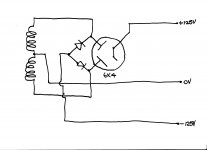
With the rectification shown below, doesn't each leg have a SS diode and a vacuum diode making it balanced?
I have 2 6X4s already in place so I could certainly go to 2 hybrid bridges.
Attachments
With the rectification shown below, doesn't each leg have a SS diode and a vacuum diode making it balanced?
No! That's 2X FWCT setups wired back to back. The negative rail is SS rectified and the positive rail is vacuum rectified. The schematic looks like a bridge, but that's not the case. Cover either the SS diodes or the vacuum rectifier up and you'll see what's really going on.
I still don't see what's the problem with that?
In isolation, no problem exists. However, the OP clearly stated that vacuum rectification was desired and the performance of hybrid bridge rectifiers is completely dominated by the vacuum diodes. As much as reality will allow, I'm trying to provide a have the cake and eat it too situation.
Wow… I'm late to the party … but there does appear to be an obvious solution: employing a separate filament transformer for the 'reverse direction' pair of vacuum rectifiers in charge of lighting up the negative rail. They're cheap, they work, they usually have sufficient hi-pot insulation.
Maychance like this?
Just asking,
GoatGuy ✓
Maychance like this?
Just asking,
GoatGuy ✓
Attachments
Thanks Eli. Is this what you have in mind?No! That's 2X FWCT setups wired back to back. The negative rail is SS rectified and the positive rail is vacuum rectified. The schematic looks like a bridge, but that's not the case. Cover either the SS diodes or the vacuum rectifier up and you'll see what's really going on.

Dave.
New split rail supply with hybrid bridge
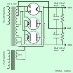
So, reusing all the existing components the original 2x 250V supply will now look like this:

with attention paid to the polarity of the electrolytics of course.
The HT secondary of one of the transformers will no longer be used. One of the other secondaries will still be providing heater supply to one of the twin diodes while the 3rd secondary will still be supplying the rectified heater supply to 3 of the 6 filter tubes.
It's tempting to take one of the transformers out altogether. The remaining transformer has plenty of capacity to supply the heaters of both twin diodes and all 6 filter tubes.
So, reusing all the existing components the original 2x 250V supply will now look like this:
with attention paid to the polarity of the electrolytics of course.
The HT secondary of one of the transformers will no longer be used. One of the other secondaries will still be providing heater supply to one of the twin diodes while the 3rd secondary will still be supplying the rectified heater supply to 3 of the 6 filter tubes.
It's tempting to take one of the transformers out altogether. The remaining transformer has plenty of capacity to supply the heaters of both twin diodes and all 6 filter tubes.
Looking good. You may need bleeder resistors across C3 & C4, to ensure that the critical current is drawn.
While the vacuum rectifiers should block any SS diode generated switching noise, Schottkys (instead of PN parts) guarantee said noise will not be generated, to begin with.
While the vacuum rectifiers should block any SS diode generated switching noise, Schottkys (instead of PN parts) guarantee said noise will not be generated, to begin with.
Thanks Eli. I have a bunch of suitable Schottkys and that's what I'll use.While the vacuum rectifiers should block any SS diode generated switching noise, Schottkys (instead of PN parts) guarantee said noise will not be generated, to begin with.
dch₅₃;6007361 said:So, reusing all the existing components the original 2× 250V supply will now look like this:
View attachment 801680
with attention paid to the polarity of the electrolytics of course.
The HT secondary of one of the transformers will no longer be used. One of the other secondaries will still be providing heater supply to one of the twin diodes while the 3rd secondary will still be supplying the rectified heater supply to 3 of the 6 filter tubes.
It's tempting to take one of the transformers out altogether. The remaining transformer has plenty of capacity to supply the heaters of both twin diodes and all 6 filter tubes.
I really must be missing something …
The (nicely drawn) power supply will NOT be a soft-on power supply, for one. The use of silicon rectifiers in both the upper and lower sections overrides the effect of the cross-associated valves.
If overridden, then what is the point of having the valves, to begin with?
I'm very tired … no sleep last night.
I'm open to, and will welcome correction from 'the bench'.
Go for it, goats.
-= GoatGuy✓ =-
The CT of the rectifier winding is connected to both bridges and nothing else. The ends of the rectifier winding are connected to a single bridge and nothing else. The current path in both of the bridges is through the slow to warm 6X4 cathode sleeve. Remember, PSUs are differential and we arbitrarily ground some point.
Trafo connected only to bridges and PSU filters connected only to bridges, is the state of affairs. In both bridges, the "juice" is always passing through a single SS diode and a single vacuum diode.
Trafo connected only to bridges and PSU filters connected only to bridges, is the state of affairs. In both bridges, the "juice" is always passing through a single SS diode and a single vacuum diode.
So, what voltages should I expect from my hybrid bridges and chokes?
My split rail hybrid bridge supply is built but didn't give me the voltages I was expecting.
The original supply looked like this:

There's 200V RMS across each winding. Output is ~250V DC with a draw of 10mA.
I'm puzzled by that because there's supposed to be significant HT loss across the vacuum diodes and the choke filtering gives ~0.9Vin.
The new supply, and here's the schematic again:

gave me +219V and -216V or thereabouts with 12K loads. I was expecting ±125V.
I'm using "gave" because after a minute or so there was a flash from underneath the chassis. The 6X4s weren't visible with the chassis upside-down but I'm guessing that sadly, it maybe one of them.
So, not the voltages I was expecting and one of the twin diodes may be deceased. I'll test them by plugging them into the stereo counterpart which is still as originally built.
My split rail hybrid bridge supply is built but didn't give me the voltages I was expecting.
The original supply looked like this:
There's 200V RMS across each winding. Output is ~250V DC with a draw of 10mA.
I'm puzzled by that because there's supposed to be significant HT loss across the vacuum diodes and the choke filtering gives ~0.9Vin.
The new supply, and here's the schematic again:
gave me +219V and -216V or thereabouts with 12K loads. I was expecting ±125V.
I'm using "gave" because after a minute or so there was a flash from underneath the chassis. The 6X4s weren't visible with the chassis upside-down but I'm guessing that sadly, it maybe one of them.
So, not the voltages I was expecting and one of the twin diodes may be deceased. I'll test them by plugging them into the stereo counterpart which is still as originally built.
As drawn, you have a CLC filter. 😡 C1 and C2 need to be 0.01 μF., for choke I/P behavior being exhibited. C1 & C2 are present to suppress inductive kick back spikes, not to charge up to VP. The WVDC of those suppressor caps. needs to be very high.
Choke I/P filtering yields approx. 0.9 VRMS, if and only if the critical current is drawn. Put 15 Kohm bleeder resistors of appropriate wattage capability across C3 and C4.
Choke I/P filtering yields approx. 0.9 VRMS, if and only if the critical current is drawn. Put 15 Kohm bleeder resistors of appropriate wattage capability across C3 and C4.
Thanks Eli.
When I posted earlier I hadn't actually pulled the capacitors out. It was only when I pulled them out that I found they were actually 10uF 400V caps.
I'll replace them with 0.01uF caps.
The 6X4s are OK but that raises the question of where the flash came from.
I need to do something about the fuses. 5A to survive the turn-on won't protect anything!
Dave.
My split rail hybrid bridge supply is built but didn't give me the voltages I was expecting.
The original supply looked like this:
View attachment 803075
There's 200V RMS across each winding. Output is ~250V DC with a draw of 10mA.
I'm puzzled by that because there's supposed to be significant HT loss across the vacuum diodes and the choke filtering gives ~0.9Vin.
The new supply, and here's the schematic again:
View attachment 803076
gave me +219V and -216V or thereabouts with 12K loads. I was expecting ±125V.
I'm using "gave" because after a minute or so there was a flash from underneath the chassis. The 6X4s weren't visible with the chassis upside-down but I'm guessing that sadly, it maybe one of them.
So, not the voltages I was expecting and one of the twin diodes may be deceased. I'll test them by plugging them into the stereo counterpart which is still as originally built.
Dave,
I'm also confused as to what you want and why? Maybe if you explained a bit more it would help?
But what you have built is a +220 /0/ -220 volt supply, not a +125 /0/ -125 volt supply... you cannot get +/- 125 volts from your transformer if you use a 4 diode bridge(s).
Dave,
I'm also confused as to what you want and why? Maybe if you explained a bit more it would help?
But what you have built is a +220 /0/ -220 volt supply, not a +125 /0/ -125 volt supply... you cannot get +/- 125 volts from your transformer if you use a 4 diode bridge(s).
Hi Alan,
Thanks for your reply.
I'll have to hit the high points otherwise this will fill many pages!
I'm modifying a 4-way tube crossover for someone else. I didn't built it. There's a left power supply chassis and separate filter chassis and a right power supply chassis and separate filter chassis.
Each power supply chassis contains 2 completely independent twin diode (6X4) HT supplies and 2 completely independent 12.6V DC heater supplies; lots of big capacitors in both the power supply and filter chassis.
Each power supply chassis is connected by 2 separate umbilicals to a filter chassis, containing a low pass filter, 2 band pass filters and a high pass filter, all 18dB.
The power supplies are outrageous overkill. There are loads of other problems with the original design and implementation but let's not go there.
The HT supplies currently put out 250V. But each one only supplies 3 12AX7s for a total of around 10mA.
What I want to end up with is ±125V HT for a bunch of reasons:
- no bias resistors required
- no protection diodes required
- filter capacitors can be low voltage types because all signal paths are referenced to 0v
- no DC blocking capacitors required
- I can use constant current sources in the cathode followers to reduce distortion.
I thought I could get ±125V from what was previously one of the +250V supplies.
Maybe I could use half the HT winding one transformer and half the HT winding of the other.
Dave.
Last edited:
There are 2 ways to obtain a full wave rectified bipolar PSU from a CT winding. The commonly seen method employs what looks like a 4 diode bridge across the ends of the rectifier winding, but is (in fact) 2X FWCT setups wired back to back. The OP is using the less commonly seen method of 2X bridges, where the rectifier winding's CT is not directly connected to ground.
Each of the hybrid bridges is fed by only 1/2 of the rectifier winding.
Each of the hybrid bridges is fed by only 1/2 of the rectifier winding.
- Home
- Amplifiers
- Tubes / Valves
- Can a pair of twin tube diodes be used to generate split rails?