> total of around 10mA. What I want to end up with is ±125V
I can't grasp all your requirements. However for the question "Can a pair of twin tube diodes be used to generate split rails?", YES. If they are the right "twin diodes".
For a small load, 6AL5 may do. This plan apparently runs right AT 6AL5's published ratings; PSUD complains of half-volt over-rating and large peak current at start-up (750r seems to tame that).
Attachments
Choke I/P filtering yields approx. 0.9 VRMS, if and only if the critical current is drawn. Put 15 Kohm bleeder resistors of appropriate wattage capability across C3 and C4.
Thanks again Eli.
I removed the 10uF capacitors. I'll replace them with 0.01uf caps when I have the supply up-and-running.
I have 12k 7.5W bleeder resistors in place which are the closest to 15k that I have.
This time I measured +151V and -94V before there was a flash again after a few seconds and I switched off.
I must have an error somewhere. If I can't find it and the 6X4s are still OK I'll run the test with the top-side of the power supply visible so I can see where the flash is occurring.
I'm going to buy some 200mA and 500mA slow-blow fuses this afternoon too.
> total of around 10mA. What I want to end up with is ±125V
I can't grasp all your requirements. However for the question "Can a pair of twin tube diodes be used to generate split rails?", YES. If they are the right "twin diodes".
For a small load, 6AL5 may do. This plan apparently runs right AT 6AL5's published ratings; PSUD complains of half-volt over-rating and large peak current at start-up (750r seems to tame that).
I have 2 250V supplies like this

and I would like one ±125V supply. Current requirement is around 20mA; enough to drive 6 12AX7s anyway.
Preference is to retain the vacuum tube diodes and not to have to add further chokes and capacitors.
Thanks for the PSUD suggestion. I have it and should have been using it.
Hi Dave,
Unfortunately things have gotten a little mixed up in this thread...
The question you asked has been answered, you can use 'tube rectifiers' for a split rail supply. There are several examples shown.
The supplementary and probably the better question now is, 'can I get one ±125V supply from the components I already have?' Answer as I said before is no. Not the way you are trying to with what you have any way.
The problem is the voltage you have from the secondaries of the transformer. You mentioned 200-0-200 volts ac. That suits the original bi-phase tube rectifier perfectly to get you 250 volts DC. (Only one side of the secondary is used per cycle, so you get full wave rectification and so 250 volts into caps.)
Once you start to use 'bridge rectification' to split the rails then each half of the 200-0-200 winding add together so effectively you have a 400 volt ac transformer. Hence the ±250V DC results you got first...
To achieve what you want (as described above) you have to halve the secondary voltage to 100-0-100. Not sure that is practical though.
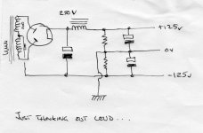
One solution might be to retain the original bi-phase rectifier as is. Then provide a false centre tap with 2 resistors and capacitors following the choke.
There are limitations though, the transformer centre tap Must Not go to ground or the chassis, and the current draw for each half (each 125v) must be equal all the time.
Alan
Unfortunately things have gotten a little mixed up in this thread...
The question you asked has been answered, you can use 'tube rectifiers' for a split rail supply. There are several examples shown.
The supplementary and probably the better question now is, 'can I get one ±125V supply from the components I already have?' Answer as I said before is no. Not the way you are trying to with what you have any way.
The problem is the voltage you have from the secondaries of the transformer. You mentioned 200-0-200 volts ac. That suits the original bi-phase tube rectifier perfectly to get you 250 volts DC. (Only one side of the secondary is used per cycle, so you get full wave rectification and so 250 volts into caps.)
Once you start to use 'bridge rectification' to split the rails then each half of the 200-0-200 winding add together so effectively you have a 400 volt ac transformer. Hence the ±250V DC results you got first...
To achieve what you want (as described above) you have to halve the secondary voltage to 100-0-100. Not sure that is practical though.
One solution might be to retain the original bi-phase rectifier as is. Then provide a false centre tap with 2 resistors and capacitors following the choke.
There are limitations though, the transformer centre tap Must Not go to ground or the chassis, and the current draw for each half (each 125v) must be equal all the time.
Alan
Attachments
Hi disco,
I think that results in 2 positive supplies with respect to ground?
The OP is asking for a 125v positive and a 125v negative supply with respect to ground.
I think that results in 2 positive supplies with respect to ground?
The OP is asking for a 125v positive and a 125v negative supply with respect to ground.
You are right, 'nother theme then 🙂
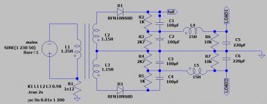
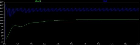
A lot of fiddling with the R2/R3 combination to arrive at the target voltage and a 'slow' supply to boot, unless you can burn 50mA or so in the process. Output voltage stability highly depends on the load current being constant, I would not recommend this setup without some form of stabilisation.
A lot of fiddling with the R2/R3 combination to arrive at the target voltage and a 'slow' supply to boot, unless you can burn 50mA or so in the process. Output voltage stability highly depends on the load current being constant, I would not recommend this setup without some form of stabilisation.
Last edited:
Hi Dave,
Unfortunately things have gotten a little mixed up in this thread...
The question you asked has been answered, you can use 'tube rectifiers' for a split rail supply. There are several examples shown.
The supplementary and probably the better question now is, 'can I get one ±125V supply from the components I already have?' Answer as I said before is no. Not the way you are trying to with what you have any way.
The problem is the voltage you have from the secondaries of the transformer. You mentioned 200-0-200 volts ac. That suits the original bi-phase tube rectifier perfectly to get you 250 volts DC. (Only one side of the secondary is used per cycle, so you get full wave rectification and so 250 volts into caps.)
Once you start to use 'bridge rectification' to split the rails then each half of the 200-0-200 winding add together so effectively you have a 400 volt ac transformer. Hence the ±250V DC results you got first...
To achieve what you want (as described above) you have to halve the secondary voltage to 100-0-100. Not sure that is practical though.
One solution might be to retain the original bi-phase rectifier as is. Then provide a false centre tap with 2 resistors and capacitors following the choke.
There are limitations though, the transformer centre tap Must Not go to ground or the chassis, and the current draw for each half (each 125v) must be equal all the time.
Alan
Thanks very much for the explanation Alan. I should have started a separate thread.
Since I've now wired up Eli's schematic I'll see it through till it's working properly. With the HT drop across the tube rectifiers and 0.9Vin with the choke filtering, if I get down to to around ±160V that might suffice.
Otherwise, I'll have to go back to the original +250V supply.
I'll checkout your proposal too.
Dave.
You can use 4 identical damper diodes, like my project. As the isolation between cathode and heater is very good in this diodes, you don't need different secondaries for them. My diodes are 6AX3 or 6BE3, very similar between them. With a toro hand wound it gives me ±275V choke input to the filter.
Attachments

Last edited:
Thanks again Eli.
I removed the 10uF capacitors. I'll replace them with 0.01uf caps when I have the supply up-and-running.
I have 12k 7.5W bleeder resistors in place which are the closest to 15k that I have.
This time I measured +151V and -94V before there was a flash again after a few seconds and I switched off.
I must have an error somewhere. If I can't find it and the 6X4s are still OK I'll run the test with the top-side of the power supply visible so I can see where the flash is occurring.
I'm going to buy some 200mA and 500mA slow-blow fuses this afternoon too.
I suspect you have a capacitor in the negative supply connected backwards.
I suspect you have a capacitor in the negative supply connected backwards.
Thanks kodabmx. I was very particular about the polarity of the capacitors and have checked them multiple times. I've seen what even a small electrolytic connected the wrong way around can do.
The positive supply is working fine and producing +174V across C3 and +164V across C5 with 12K bleeder resistors across C3 and C5.
To get down to the voltage I need I can always increase the value of R1 and R2 and get better filtering as well.

I'll get back to the negative supply but Christmas shopping and preparations must be done!
You can use 4 identical damper diodes.
Thanks for the suggestion Osvaldo. I'll persevere with what I have. Really keen to avoid changing existing components. The large capacitors are all glued into place. Transformers and chokes are a given too.
Choke input seems such an unnecessary burden on your design. But that's another topic. How much imbalance do you anticipate between the positive and negative supplies? Assuming, since we haven't seen the circuit, that you're intending to feed a bunch of cathode followers, the imbalance would be a matter of filter capacitor leakage and some tiny grid current.
Alan's post #44 seems by far the most straightforward, and least wasteful, with those assumptions. And, you can use both chokes, one in the positive half, one in the negative, effectively in series, minimizing bleeder/ balancer draw.
All good fortune,
Chris
Alan's post #44 seems by far the most straightforward, and least wasteful, with those assumptions. And, you can use both chokes, one in the positive half, one in the negative, effectively in series, minimizing bleeder/ balancer draw.
All good fortune,
Chris
Choke input seems such an unnecessary burden on your design. But that's another topic. How much imbalance do you anticipate between the positive and negative supplies? Assuming, since we haven't seen the circuit, that you're intending to feed a bunch of cathode followers, the imbalance would be a matter of filter capacitor leakage and some tiny grid current.
Alan's post #44 seems by far the most straightforward, and least wasteful, with those assumptions. And, you can use both chokes, one in the positive half, one in the negative, effectively in series, minimizing bleeder/ balancer draw.
Chris
Thanks Chris.
As soon as I get the problem in the negative supply fixed I’ll revisit Alan’s suggestion.
Yes, 6 cathode followers.
Why is the choke a “burden”? It’s already there so why not use it?
I'm having a hard time keeping up. Can I assume that your schematic in post #51 is not actually real? And that the original power supply was not actually choke input?
Was the original supply two identical conventional cap input supplies, each producing about +250 VDC, and the choke(s) were purely for filtering? If so, and your wish is solely to move the ground reference point of the DC supplies to about half way, Alan's recommendation is all you'll need. The divider resistors need only be small enough R to dominate any stray circuit imbalances, and can be placed upstream of the chokes. 5 to 10 mA draw should be way more than enough - call it 15K each at 125VDC.
All good fortune,
Chris
Original 2 +250V supplies vs single split-rail dual hybrid bridge supply
The original supply was two identical CLC supplies producing 250V. They looked like this:

Based on Eli's suggestion to obtain split rails I have added some Shottky diodes and modified the original 2 supplies to produce a single split rail supply (C1 and C2 haven't been added yet):

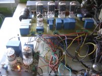
With 12k bleeder resistors across C1 through C4 (suggested by Eli to ensure the choke passes sufficient current to work properly), rather than the desired ±125V the output voltages are currently +164V and -91V, the latter until the negative rail 6X4 suddenly glows red and there is a flash in the tube at which point I turn the whole thing off. The offending twin diode still works fine in the other power supply which is still configured as 2 +250V supplies.
The red glow and subsequent flash are happening in the central heater/cathode area of the tube.
Since I have gone to all the trouble of wiring the whole split-rail twin hybrid bridge supply up my current plan is to resolve problem before going on to look at Alan's suggestion.
I'm having a hard time keeping up. Can I assume that your schematic in post #51 is not actually real? And that the original power supply was not actually choke input?
Was the original supply two identical conventional cap input supplies, each producing about +250 VDC, and the choke(s) were purely for filtering? If so, and your wish is solely to move the ground reference point of the DC supplies to about half way, Alan's recommendation is all you'll need. The divider resistors need only be small enough R to dominate any stray circuit imbalances, and can be placed upstream of the chokes. 5 to 10 mA draw should be way more than enough - call it 15K each at 125VDC.
Chris
The original supply was two identical CLC supplies producing 250V. They looked like this:
Based on Eli's suggestion to obtain split rails I have added some Shottky diodes and modified the original 2 supplies to produce a single split rail supply (C1 and C2 haven't been added yet):
With 12k bleeder resistors across C1 through C4 (suggested by Eli to ensure the choke passes sufficient current to work properly), rather than the desired ±125V the output voltages are currently +164V and -91V, the latter until the negative rail 6X4 suddenly glows red and there is a flash in the tube at which point I turn the whole thing off. The offending twin diode still works fine in the other power supply which is still configured as 2 +250V supplies.
The red glow and subsequent flash are happening in the central heater/cathode area of the tube.
Since I have gone to all the trouble of wiring the whole split-rail twin hybrid bridge supply up my current plan is to resolve problem before going on to look at Alan's suggestion.
... The red glow and subsequent flash are happening in the central heater/cathode area of the tube ...
You may be exceeding the heater / cathode insulation specification of the negative 6X4? (Spec is 100 volts positive with respect to the cathode.)
You will have to explain how you have wired up the heater supplies to the 2 rectifiers. Do they share a common 6.3 volt supply? Do they share the same 6.3 volt supply as the other valves? Does the 6.3 volt supply get a ground reference? etc.
Could be the negative 6X4 will require its own isolated heater supply?
...and I would not trust the ones that have been glowing red...
Why does my negative rail bridge object to being earthed?
To establish the cause of my negative rail hybrid bridge failure I replaced the valuable 6X4 with a pair of more robust 3A Schottky diodes and gradually removed links while sacrificing some 5A fuses. I ended-up with this:

I've established that a fuse will always blow if the joint of the cathodes on the left is earthed.
I reintroduced the LCRC filter components without earthing the 0V side and a steady -160V resulted from an input of 208VAC.
Having replaced the 6X4 twin diode with Schottkys I was expecting a higher voltage than the +164V I was getting from the positive rail section.
I checked whether the toroidal mains transformer might have had a short to the chassis. No short.
Here's the full schematic again (keep in mind that the voltages I've measured are +164V and -160V (albeit with the earth disconnected):

I've racked my brains. Does anyone have any suggestions why one side of my bridge objects to being earthed please?
To establish the cause of my negative rail hybrid bridge failure I replaced the valuable 6X4 with a pair of more robust 3A Schottky diodes and gradually removed links while sacrificing some 5A fuses. I ended-up with this:
I've established that a fuse will always blow if the joint of the cathodes on the left is earthed.
I reintroduced the LCRC filter components without earthing the 0V side and a steady -160V resulted from an input of 208VAC.
Having replaced the 6X4 twin diode with Schottkys I was expecting a higher voltage than the +164V I was getting from the positive rail section.
I checked whether the toroidal mains transformer might have had a short to the chassis. No short.
Here's the full schematic again (keep in mind that the voltages I've measured are +164V and -160V (albeit with the earth disconnected):
I've racked my brains. Does anyone have any suggestions why one side of my bridge objects to being earthed please?
You may be exceeding the heater / cathode insulation specification of the negative 6X4?
...and I would not trust the ones that have been glowing red...
Thanks Alan.
Having replaced the twin diode with Schottkys and still had the problem suggests cathode/heater differential isn't the problem.
The cathode is actually earthed so heater/cathode differential shouldn't be a problem.
That said, the 6X4s in the original +250 supplies (4 in-total) have heater/cathode differentials well in excess of 100V. They've operated with no heater elevation for some years. If I can successfully get lower voltage split rails the problem will be alleviated somewhat.
I will order replacements for the 6X4 that has been abused. That's excellent advice!
Dave.
...
I've racked my brains. Does anyone have any suggestions why one side of my bridge objects to being earthed please?
First 'logical' answer is that either D3 or D4 is leaky or short... So what you have is a half wave rectifier? If D3/4 are good, you should not measure any -ve voltage at their junction? There is no return path... but you have one somewhere.
Yes not relevant right now....
Having replaced the twin diode with Schottkys and still had the problem suggests cathode/heater differential isn't the problem.
- Home
- Amplifiers
- Tubes / Valves
- Can a pair of twin tube diodes be used to generate split rails?