The prototype I posted above puts all the controls in each cell. I think it's nice to be able to see all of them, but the downside is that each cell gets quite big. An alternative could be to do like in the Motu app, and just have a small colored square showing if it's active or not. Then clicking it could open a dropdown with the controls.
Motu seems to use just blue to show the status, but it would be possible to let the color indicate the gain, using a scale such as this:

Motu seems to use just blue to show the status, but it would be possible to let the color indicate the gain, using a scale such as this:
A design stage/page where defining mixers in an arbitrary order for later use, as per today don't aid me in designing a system. On a high level, the Mixers are the skeleton of a system design and filters are the soft parts - bad skeleton and no woking system.
So I would like to see a design flow that must start with the incoming mixer and then any following intermediate and in the end the "out" mixer. The ones, if any, in-between may perhaps be possible to shuffle around (and added/deleted) between the in and out mixer.. don't know.. So I suppose in one sense one would create the Pipeline skeleton i.e. both mixers and their order in one integrated design flow stage.
Having this, one can think in the signal flow terms while doing it... this comes in, is splited into this because I want local EQ and delay in this arm, joins here with that branch and then combines all where I do global EQ.... sort of...
It would need for screen estate reasons be a vertical process with incoming on top...
If one could see the skeleton in a horizontal view during the design process as objects and fields are defined, i.e. before commit, would be a "bone".
?
//

@TNT That makes a lot of sense, each mixer is not very likely to be used more than once in a pipeline so it would be more logical to define them directly in the pipeline view. The problem with implementing something like this is simply that it would be very time consuming. The current way, with separate UIs for defining the mixers, filters, pipeline etc means that each tab is rather isolated, and that really helps to keep complexity down. A more integrated pipeline editing UI would definitely be great, but I don't think that I could build something like that in a reasonable time without working on it full time.
Here is a mockup of the dropdown approach:

I like that it becomes much more compact, I think this can make it easier to overview even if there is less detail in each cell.
I like that it becomes much more compact, I think this can make it easier to overview even if there is less detail in each cell.
Isn't it better to rest and go for the final wanted position? I'm not sure it would for me be a great help. One should not underestimate what people have already learned and the work to re-learn...
I mean, it works as is.... 🙂
//
I mean, it works as is.... 🙂
//
Just throwing it out there, I like the existing Mixer interface. I also think it can be easily visualized in the Pipeline flow diagram.
Michael
Michael
Well, I can kind of understand why you like the first Motu matrix example.
I agree with Michael that the pipeline flow diagram makes it easy to visualise. For instance when I was building the attached pipeline I was going back and forward between config of the mixers, pipeline flow diagram and config of the pipeline until it made sense.
Which reminds me Henrik, could you add to the top of the Pipeline tab display, the icon to add a step and the icon to display the pipeline. That would save having to scroll down to the bottom, and if a step is added using the add step icon at the top, then place the new step at the top and require it to be "downed" rather than "upped" from the bottom. Would be especially good for adding an input filter to a long config.
Attachments
I meant full time as in full normal working days. Working on such a big task for a few hours here are there in the evenings won't be enough to make any meaningful progress.Isn't it better to rest and go for the final wanted position?
The existing mixer ui works, but it has some issues:
- difficult to see what a mixer does, you need to plot the pipeline to see it. Especially for a mixer with many input and output channels, when it becomes quite large.
- it allows defining some weird mixers, like having two mappings with the same destination channel, or the same source twice in a mapping. This is technically allowed but is more confusing than useful.
- it's clunky to select both source and destination channel in numeric fields (and this doesn't work well with channel labels)
Two good ideas, will do!could you add to the top of the Pipeline tab display, the icon to add a step and the icon to display the pipeline. That would save having to scroll down to the bottom, and if a step is added using the add step icon at the top, then place the new step at the top and require it to be "downed" rather than "upped" from the bottom.
Hi all, my first post. Thanks Henrik for a fantastic package that I have set up (V2) with guidance from MDSimon's excellent tutorials. It is all working perfectly with FIR based crossover, with one exception - when I try to use REW and RePhase to do room correction there seem to be random impulses generated. The mess up the scans completely, both SPL and timing phase are messed up.
For background, my set-up chain is:
TV -> TosLink -> USB converter -> PC -> Topping DM7 DAC.
For the REW measurements:
UMIK-1 -> Laptop -> HDMI audio -> TV.
If anyone could suggest how to diagnose where the impulses might come from, or how to fix this, I would be very grateful.
There is no clipping detected (signal levels are well down and no boost in the config), in fact CDSP does not report any anomalies in the log. I suspect there may be some sort of timing issue, but not sure how that could slip through CDSP's diagnostics. REW generates 48kbit audio to the TV, which always uses 48kbit PCM to CDSP.
Thanks heaps from Perth Australia.
2 cents some buffer issues. Please describe your chain in detail, where CDSP amd REW are, how it's all linked up.
For music: Android TV -> TosLink -> USB converter -> CDSP(on PC) -> Topping DM7 DAC.
This works without error.
With REW involved: UMIK-1 -> REW on Laptop -> HDMI audio -> TV -> TosLink -> USB converter -> CDSP -> Topping DM7 DAC -> Amp
I am running at 192000 samples/s with Asyncsinc resampling. DSP load sits around 2-6%. I have 1024 chunk size and target level 512.
BUT, there is no report of buffer underrun in the log.
Could the REW signal going to the TV have some timing jitter around the 48kb/s that then messes with the resampling in CDSP?
Last edited:
Which OS/HW, what output used for REW?UMIK-1 -> REW on Laptop -> HDMI audio -> TV
Which OS/HW?-> TosLink -> USB converter -> CDSP -> Topping DM7 DAC -> Amp
This target level means you are pushing your output buffer to be on average filled with only one half of the chunk, measured after full chunk delivery. For alsa I would recommend to raise to 75% of the buffer size (logged in debug logs or alsa /proc/asound files). For windows at least one chunk.I have 1024 chunk size and target level 512.
I do not see any technical way how that could happen.Could the REW signal going to the TV have some timing jitter around the 48kb/s that then messes with the resampling in CDSP?
IMO it's important to test parts of your chain, e.g. the HDMI/toslink loopback to check your TV :
REW on Laptop -> HDMI audio -> TV -> TosLink -> USB converter -> REW
and UMIK:
UMIK-1 -> REW on Laptop -> HDMI audio -> TV speakers
Thank you for your help. REW runs under Windows 10 on a ThinkPad, CDSP on a Think centre under Debian 12.
I checked REW to the TV speakers (good thinking!) - that chain seems to be the source of the glitches. What would be the best way to input REW scans from the laptop into the CDSP system i.e. avoid the HDMI & TV part of the chain?
Thanks again, phofman.
I checked REW to the TV speakers (good thinking!) - that chain seems to be the source of the glitches. What would be the best way to input REW scans from the laptop into the CDSP system i.e. avoid the HDMI & TV part of the chain?
Thanks again, phofman.
So the TV is used just as a bridge between the Thinkpad running REW on windows and Thinkcentre running CDSP on linux?
If the debian has GUI installed and the thinkcentre has enough CPU power, you could run REW directly on debian, playing to alsa loopback device -> CDSP.
If the debian has GUI installed and the thinkcentre has enough CPU power, you could run REW directly on debian, playing to alsa loopback device -> CDSP.
Unfortunately, I have no GUI on the CDSP ThinkCentre, so loaded up REW on another old laptop, and that worked perfectly...must be a cable/connector issue. My apologies for the wild goose chase! Thank you for pointing me in the right direction.
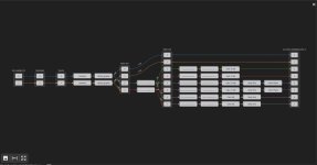
Some more experimentation with the mixer UI. This mostly works now:

Clicking a + enables the cell, and clicking a cell opens the popup with the controls.
It's missing the channel labels, and a colorbar to show what gain the colours mean. I also haven't looked at how to show muted and inverted status yet.
Clicking a + enables the cell, and clicking a cell opens the popup with the controls.
It's missing the channel labels, and a colorbar to show what gain the colours mean. I also haven't looked at how to show muted and inverted status yet.
For "gain" write the number in black over the green, "muted" change to a washed out light green, "inverted" change the green to purple (or blue or yellow etc).a colorbar to show what gain the colours mean. I also haven't looked at how to show muted and inverted status yet
What does Motu do for the device you showed in your example ?
- Home
- Source & Line
- PC Based
- CamillaDSP - Cross-platform IIR and FIR engine for crossovers, room correction etc