I am not sure how to output samples in a standalone application. If you opt for another alsa device, it will duplicate the alsaloop functionality which does adaptive resampling too and you would code stuff not required by your project. I think a well-commented rust source code would itself be a major help.
I will start simple, with reading and writing as raw binary. I can just copy the read/write code from "file" device in CamillaDSP. And I already have Python scripts for generating and analyzing the data.I am not sure how to output samples in a standalone application. If you opt for another alsa device, it will duplicate the alsaloop functionality which does adaptive resampling too and you would code stuff not required by your project. I think a well-commented rust source code would itself be a major help.
It's recommended (almost mandatory) to include simple examples in Rust libraries. A raw in/out resampler is perfect for this.
Here is an example, a simple rust library I wrote for reading and writing tags in .ogg files: GitHub - HEnquist/lib-rust-oggvorbis-meta. In the "examples" folder you put one or several short programs that demonstrate how to use the library.
Hello here...
I'am (trying) to build some fir filters for this beautiful CamillaDSP engine, and while asking some quistions at this thread https://www.diyaudio.com/forums/multi-way/221434-rephase-loudspeaker-phase-linearization-eq-fir-filtering-tool-299.html#post6159915
At post #2984 i realised that i don't know about filter lengths and soo, seeing what fluid replied to me, maked me post this post now.
I hope i can have some explanation of what kind of filter to and what format i need (filter length's etc...)
## See attached picture too 🙂
I use REW and RePhase for the room correction.
Jesper.
Attachments
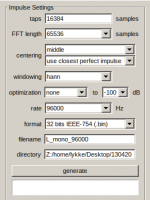
It's not really possible to answer how long your filters should be, that really only depends on what you want to achieve!
But one can say a few things. Long filters are mostly useful for correcting low frequencies. Then it's not the length of the impulse response in samples that's important, but the length in time. So the filter at 96kHz should be twice as long (in samples or taps) as the one for 48 kHz to give the same result.
About format. Text is fine and have the advantage that it's human readble, but is slower to import and the files get quite big. I would recommend 64-bit floats (often called "double") if you are running 64-bit (the default), or 32-bit floats ("single" or sometimes "float") if you compiled CamillaDSP for 32-bit mode. Then there is no conversion needed when reading.
It' useful not only for In-Out:...when the source and sink are using different clock sources. ...
Think of an X-Over, e.g. with 4 ways, each feeding a different 2-Channel DAC. If every of these 4 ways has his own resampler to catch up for the 4 different clocks of the DAC, then no more need to sychronzie these devices. This would be a very nice option, e.g. also in case you are scaling up a system by including some channels later on (a subwoofer p.ex.).
So in terms of camilladsp a high-quality SRC filter would indeed be a super option and something unseen until now.
I am not sure about performance when two unsynchronized DACs were used for multichannel. While adaptive resampling avoids buffer under/overflows (serial mode), it would not maintain interchannel frames synchronization in parallel mode, only in long run.
Outputting to several independent dacs is probably never going to work well for a crossover. If we cross over at 2kHz and run 44100Hz, that means each single sample we are off adds a phase difference of 16 degrees. And I think it would be already be a challenge to make sure they stay within maybe +-100 samples.
I'm planning to put the resampling on the capture side. That means for let's say a stereo 2-way crossover only two channels need to resampled. It the resampling was at the playback side, that would instead be four and use twice the cpu time.
I'm planning to put the resampling on the capture side. That means for let's say a stereo 2-way crossover only two channels need to resampled. It the resampling was at the playback side, that would instead be four and use twice the cpu time.
Some testing along with CamillaDSP:
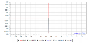
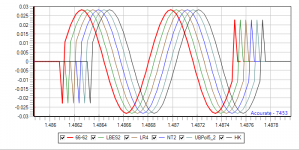
I convolved a synthetic and quite weird test signal of 65 samples length along with five different LinPhase (128k) 4-way xovers of same xfrequencies (70/420/2450), but of different types from shallow to very steep (and ringing): (L)BES2, LR4, NT2, UBPol5_2 and HK. Just to have a look how it sums up after splitting the CamillaDSP data pipe into to 2x4 channels at the begin of the pipe, inserting the filters like for a real stereo xover, but then merging everything together again at the end of the pipe. Theoretically this equals ideally an 1:1 transmission (along with some processor heating). The idea was to control wheter there is a critical filter type, where the convolving process would introduce some glitches for one reason or another. Result: Nope! Perfect convolution/summation with all types of xovers!
Time.png
Time_Zoom.png
Red is the original MinPhase test signal, artificially delayed by 65532 samples for the foto session. The other curves are the result of the 4-way-convolution after summation. They have been artificially delayed 2-sample-wise to better show theirs congruence with the original test signal.
Conclusion: Convolution does not harm and is ok with any filter type - as hopefully expected!
Attachments
Brief Addon:
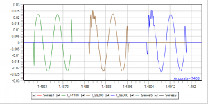
While convolution does not distort the test pulse used in the above test set, sample rate conversion (SRC) does. Same 2x4xover setup as before with 3 sets of LR4 filters (44.1/88.2/96), same input file 44.1/16. SRC was performed with 64Bit accuracy by resample_soxr --band-width 80 --phase 25. The convolver was CamillaDSP - what else?
I_Time.png
The graph shows the 3 output impulses after summing 4 channels xover. Green 44.1k -> 44.1k (no resampling), 44.1k -> 88.2k (brown), 44.1k -> 96k (blue). Brown and blue are more or less the same, so there is absolutely no point in beleiving in even and integer resampling ratios such as is advocated by some.
So now it gets interesting. How will (maybe) the new and upcoming resampler algorithm behave with this synthetic, really nasty input signal? My bet is that any resampler will fail with this test, because of the nature of this "ugly" and quasi transient input signal.
Attachments
I'll comment on this with my admittedly incomplete knowledge about the sampling theorem...
IMHO the input signal you gave is not allowed - or to rephrase slightly - it could never have come from digitizing an analogue signal as it would have had to contain frequency components above the nyquist frequency. This violates the sampling theorem, you can't sample frequencies above nyquist.
So my theory is that the resampler is excited by this transient and shows ringing in it's filter with these "unallowed" frequency components.
Hopefully somebody with better knowledge about this stuff can comment on this.
The signal is allowed, but the band-limited (at the Nyquist frequency) analog signal that generated this sampled signal would have to look quite strange.
The "problem" is that when we plot a digital signal, we tend to draw the points and connect them with straight lines. But that's not true. The sample points are really just points, and there are rules for what a band-limited signal is allowed to do in between the points. For any given series of sample points, there is exactly one band-limited signal that passes through all points.
Let's consider a short digitalized signal sampled at fs_orig: 0, 0, 0, 1, 0, 0, 0. It's a single spike, so the the frequency content of this signal is a flat line all the way up to fs_orig/2. Now we want to upsample it to twice the sample frequency, fs_new = 2*fs_orig.
The simple way would be to add points halfway between the old points by simple linear interpolation. Then it becomes 0, 0, 0, 0, 0, 0.5, 1, 0.5, 0, 0, 0, 0, 0. Nice and easy, an when we plot the result with the normal tools it looks just as the original. But then we plot the spectrum, and realize that this new signal contains stuff all the way up to the new Nyquist frequency, fs_new/2. Not what we wanted! New frequencies are distortion.
We need to add the new points in a way that doesn't add any new frequencies to the signal. The way to do that is to do sinc interpolation. This is equivalent to making a brickwall filter at fs_old/2.
Then the upsampled signal becomes: 0, 0.13, 0, -0.21, 0, 0.64, 1, 0.64, 0, -0.21, 0, 0.13, 0.
This is truncated because the sinc is actually infinitely long. If I would continue the series I would get more of the same, with the interpolated points alternating between positive and negative and getting smaller the further out we get.
We can't really work with infinite signals so we have to truncate the sinc at some length. Normally it's also multiplied with a window function to not mess up the spectrum too much when truncating.
The alternating pos/neg is the ringing you can see in the curves, and it's as expected. It is what prevents the upsampling from generating new frequencies!
Does software for 300EUR (Acourate) display the waveform by dumm linear interpolation? Apparently so, unless some proper interpolation can be enabled in settings.
IMO any combination of digital samples can be present in the stream sampled from a random analog signal.
IMO any combination of digital samples can be present in the stream sampled from a random analog signal.
I think most software uses straight lines, probably because that's what people are used to and/or it's the default in most plotting libraries. Proper sinc interpolation would be better but that becomes a lot more work and it might even be confusing. I prefer no lines at all, just the points. Then there is nothing "new" in the plot, just the plain data.Does software for 300EUR (Acourate) display the waveform by dumm linear interpolation? Apparently so, unless some proper interpolation can be enabled in settings.
IMO any combination of digital samples can be present in the stream sampled from a random analog signal.
The second point is true. No opinion needed, it's simply a true fact.
Meanwhile Uli Brüggemann sent me some graphs along with some theoretical explanations, and showed how to perform a near-perfect SRC within Acourate. Near-perfect only of course, because the sinc filter cannot be of endless length, as it should theoretically be. So, "my" initial test pulse, if it was converted near-perfectly from 44.1 to 88.2 would look like this:
TimeSincPol.png
By the way: Optically analyzing a pulse, I do strictly prefer the linear interpolation readout over a smoothed version: It's less elegantly looking of course, but much easier to discern the different samples.
TimeLinPol.png
So, now we seem to have an optical reference to compare with any possible and forthcoming version of SRC. And nota bene: smoothness is not bad at all, especially at the audio output of my DAC.
Attachments


A quick update on the resampling progress. I have the a first version working now in Rust. It's not complete yet, but getting there. It's giving the same results as the Python version but runs much faster.
Some numbers (time needed to resample 1 second of stereo audio):
44100 -> 44110 : 33 ms
44100 -> 96000 : 65 ms
44100 -> 192000: 126 ms
(yes it's supposed to be linear with output rate!)
This was on a laptop with a Ryzen 7 2700u cpu, using 64-bit floats, and all resampling artefacts below -200dB. It's of course possible to go faster by allowing the artefacts to be larger. Any improvement from -120dB or so is probably not really worth the effort, but it's fun to try anyway 🙂
It's also possible to do synchronous resampling! That saves some processing time, so for example 44100 -> 48000 can be done in 20 ms.
Very nice.
Does the resampling run in single thread, or is there any parallel processing involved? Thanks.
Does the resampling run in single thread, or is there any parallel processing involved? Thanks.
The simple test program I wrote is single thread, but the library is thread safe so there is nothing preventing doing something fancier and processing several channels in parallel. The resampling of a single channel isn't very easy to parallelize. Probably I should say, haven't actually thought much about it.Very nice.
Does the resampling run in single thread, or is there any parallel processing involved? Thanks.
I forgot the link to the repo, it's here:
GitHub - HEnquist/camillaresampler: An asyncronous resampling library written in Rust
I did not mean it should run multithreaded, I just wanted to relate the run time to consumed CPU time - whether just one core or whole CPU was involved. Thanks.
A quick 44100 -> 96000 : 65 ms
44100 -> 192000: 126 ms
(yes it's supposed to be linear with output rate!)
This was on a laptop with a Ryzen 7 2700u cpu, using 64-bit floats, and all resampling artefacts below -200dB. It's of .........
Will the accuracy be user configurable?
//
Super! What a contribution to linux precision audio processing! And it would be really great if the camilla resampler could perform stereo real-time (online) SRC on a raspberry Pi 4, or even a 3+! Maybe resorting to aforementionned options such as tweaking precision and/or let it run on 2 kernels. I am really eager to make some tests ...
Last edited:
- Home
- Source & Line
- PC Based
- CamillaDSP - Cross-platform IIR and FIR engine for crossovers, room correction etc