Ok, I lifted the 100r at pin1 of the AD712 on the left channel so that both opamp 100r's are isolated from both 712's. The trace from the scope is the same as with the 100r's connected. a flat line and then squashed up.
The voltage at pin 6 of the 5534 is 2.5v and pin 7 is 5v. On pins 6 & 7 I checked on google images what noise or ripple would like and the trace I got does not to me look like there is any ripple or noise, it was more a flat line again. I was using the 10hz to 10khz sweep.
The voltage at pin 6 of the 5534 is 2.5v and pin 7 is 5v. On pins 6 & 7 I checked on google images what noise or ripple would like and the trace I got does not to me look like there is any ripple or noise, it was more a flat line again. I was using the 10hz to 10khz sweep.
Is there a higher res schematic? Do you have any Puffin? -a hard copy?
Mooly, Looks almost identical to the 640c, The signal is connected to the relays in the way you describe, still connects though.
Puffin,
Are you getting the same fault out of the digital outs?
This will assist the process of elimination...
Attachments

Ok, I lifted the 100r at pin1 of the AD712 on the left channel so that both opamp 100r's are isolated from both 712's. The trace from the scope is the same as with the 100r's connected. a flat line and then squashed up.
The voltage at pin 6 of the 5534 is 2.5v and pin 7 is 5v. On pins 6 & 7 I checked on google images what noise or ripple would like and the trace I got does not to me look like there is any ripple or noise, it was more a flat line again. I was using the 10hz to 10khz sweep.
All that sounds OK.
I need to think some more on this as nothing at all about this fault makes any sense.
The muting relay does not pass audio when not muted. When playing the relay closes linking relay pins 6 and 8 in your diagram. Pin 7 on the relay which is the audio out line now floats.Mooly, Looks almost identical to the 640c, The signal is connected to the relays in the way you describe, still connects though.
On Puffin's player isolating the 100R's removes the relays from any suspicion. The only 'fault' they could cause when in circuit is not physically operating correctly and the contacts staying partly shorted and so shunting the audio to ground. The 100R test removes any doubts.
Ok, I lifted the 100r at pin1 of the AD712 on the left channel so that both opamp 100r's are isolated from both 712's. The trace from the scope is the same as with the 100r's connected. a flat line and then squashed up.
Did you also try this at the two points I circled in post #53. Those points are straight from the D/A convertor.
Also as you are getting more used to the scope now 🙂 do you have any idea at what sort of frequency the bass starts to become normal amplitude? The level should be constant at any frequency.
If you are not sure then if you play the sweep CD on a good player and decent speakers you will begin to hear the bass from around say 30Hz upwards. Compare the CD6 to the good player and note the time display on the player where the CD6 bass seems equal to the good player.
We can then get a good idea then of the frequency by seeing how far into the track you need to go for the bass to be normal.
"Did you also try this at the two points I circled in post #53. Those points are straight from the D/A convertor.
Also as you are getting more used to the scope now do you have any idea at what sort of frequency the bass starts to become normal amplitude? The level should be constant at any frequency.
If you are not sure then if you play the sweep CD on a good player and decent speakers you will begin to hear the bass from around say 30Hz upwards. Compare the CD6 to the good player and note the time display on the player where the CD6 bass seems equal to the good player.
We can then get a good idea then of the frequency by seeing how far into the track you need to go for the bass to be normal."
I still feel like I am playing with the scope rather than using it properly. I forgot to say that to scope the points you circled in post 53 I think would mean disconnecting everything attached to that board to get to the underneath as I am not sure it can be done from the top of the board?
I will attempt to judge the bass frequency using the CD6 and another player using the sweep tones.
You might be able to get at those points by measuring on the resistors or cap at the top of the board. The resistors on the diagram (blurry) look like 620 ohm. measure on those if you can find them.
The ten blue caps:

Are going to be these:

If all else fails start measuring at pins 3 and 5 of the opamp and work back towards the left on the diagram by identifying the resistors and caps.
The ten blue caps:
Are going to be these:
If all else fails start measuring at pins 3 and 5 of the opamp and work back towards the left on the diagram by identifying the resistors and caps.
As we are in the head scratching dept department, may i suggest the basics tests if you haven't already? before running for the scopes!
I have seen loss of bass manifest from intermittent or partial contacting in numerous areas as well as the equipment its connected to!
You may already know this, however, never underestimate the basic checks when fault finding. It's an old machine now, IMO all audio needs this attention before 'diving in' with the test gear, one at least knows all the connectivity is now stable for reliable fault location.
Generally, work from source to output.
The way to locate/ eliminate intermittency:
Having cleaned and electro lubed all external connections:
Make sure everything is on and audible, 'Wiggle the interconnect cables' routine.
No change?
Proceed to stage two:
For sensitive digital devices like CD players, make sure you have a grounding wristband at least. Touch the chassis of the machine before proceeding.
With the equipment open and off, marker pen connectors in their sockets, remove clean and electro lube all internal connections-
stay clear of the CD mech with solvents, be very careful removing the cable from the Laser mech to the servo board, not allowing adverse pressures when connecting and disconnecting.
Lube connections away from laser. Reconnect. Those Flexible Flat Cables from the CD mech are often a culprit for replacement but that machine may be prior to those.
Reassemble, check before power up, then whilst the equipment is live and sounding in to room with Cd playing, gently wiggle all internal cables/ wires/ anything that can be connected.
Then tap tap components on the circuit board. Make sure to use a non conductive instrument, like thin wood or plastic.
No change or fault location identified?
Proceed to stage three:
Precautions same as above, remove PCBs,
The servo board.
The Dac board, (which i note has CD5 written on it, perhaps there is a higher res schematic using that as a search?)
Inspect with 10 x magnifier eye piece and a very strong lamp, looking for dry or loose joints, if in doubt desolder + resolder with a quality solder, if it sets to mirror finish, good. If it doesn't it's either crap solder/ or has old solder/ or a leg/ hole has oxidised.
Give special attention to all parts that experience mechanical movements including vibration such as: Wires. The connectors into the PCBs, large components, relays, sockets.
Resolder them all.
Reassemble, check all connections. Test.
No change?
Proceed to stage four:
Fault lineage is best not to ignore, we have it here in four related machines of nearly identical circuits, to do with poor quality relays/ bad supplies to them/ incorrect wattage resistors that burn out.
Remove those relays and test them out of circuit. Careful desoldering required.
Pole to pole contacts should be measuring close to 0Ω when activated and importantly, when not activated, if they intermittent or show higher resistance, replace.
Identify if there is a supply problem to the relays. if the answer is yes...
Replace them with high quality gold plated hermetically sealed equivalents.
No change?
Proceed to stage five:
Get the test gear, Start with a scope to see where the fault is first 'seen'. Identify, post here!
I would also be expecting the occasional electrolytic cap gone bad from a 1996 machine
Last edited:

Would it not be wiser to start with the bits that are common to both channels or at the very least test the dacs in isolation?Both channels are affected wiht either single ended or balanced.
I am out today on a walk so will be on it later. I assume that for the time being I leave the 100r's disconnected?
I have probed and scoped the area around the 10 blue resistors. Some of the leads excite the scope giving the same flat line/squashed presentation, others give no read out. I assume that all the resistors are linked in some way and I can't really measure individual ones with accuracy. Tomorrow I will listen to the CD6 and and another player to attempt to determine where the bass comes in.
The blue parts are the caps. If you follow the copper print on the board from the IC pins 3 and 5 and follow the circuit diagram at the same time you will spot the resistors those pins go to and so on. You should be able to identify the parts doing that.
I had realised before I scoped around the 10 caps that they were caps and not resistors (same style as Dale resistors) and not resistors (brain fade when posting?) as I could read a couple of the values in Pf but most are too tight to the board or obscuring the print.
The trace on the schematic has to be scoped at 2 points one at one side of what looks like C13 and the other at C14. I have found C11 and there are a couple of via's in that area but seems to be nothing but noise from the those points. Without distorting the legs and risking breakage I am not sure where I go from here. C11 is a tantalum if that is of any help.
The trace on the schematic has to be scoped at 2 points one at one side of what looks like C13 and the other at C14. I have found C11 and there are a couple of via's in that area but seems to be nothing but noise from the those points. Without distorting the legs and risking breakage I am not sure where I go from here. C11 is a tantalum if that is of any help.
This will work to identify the points easily.
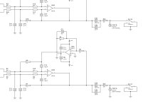
Turn the player OFF completely. Look at the circuit below and place your meter lead (on a low ohms range, not diode range) on pin 3
Use the meter to identify continuity to resistor R11 and R19. One end of R19 goes to ground so you can then identify which of the those two resistors is which. That give you the point arrowed in red to scope.
The other end of that resistor will be the point in green. You can scope there too.
And the other end of that resistor will be the point in blue. That is straight from the DAC. Scope there. Is the bass still missing at those points?
You can repeat that process to identify the parts that go to pin 5 and do the same checks. All we are looking for is whether the bass is missing at between DAC and opamp. If it is missing coming from the DAC then we really in are in unknown territory as that is totally unique (to me) as any kind of faut that can occur in the digital domain.
I have measured with the ohms setting the clump of small resistors around the 712 . The majority measure 2.02 and one 4.72, none are 2K7. All of the resistors but one are tied to ground. I could not tell you the print number of any of the resistors as they are flat against the board. I think I might have reached the limits of my incompetence/naivety 😉
I missed seeing your replies earlier 🙂 been a bit tied up with some jobs.
We're not measuring actual component values here, just what connects to where from the top of board and using that to identify the resistors concerned. You then see if the scope shows the same result of a lack of bass.
I am really struggling to make any sense of this fault as I have said, it just does not compute at all...
- Home
- Source & Line
- Digital Source
- Cambridge CD6 sound issues