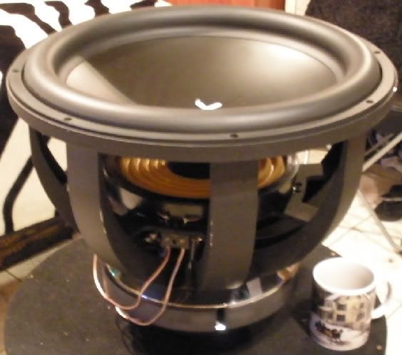
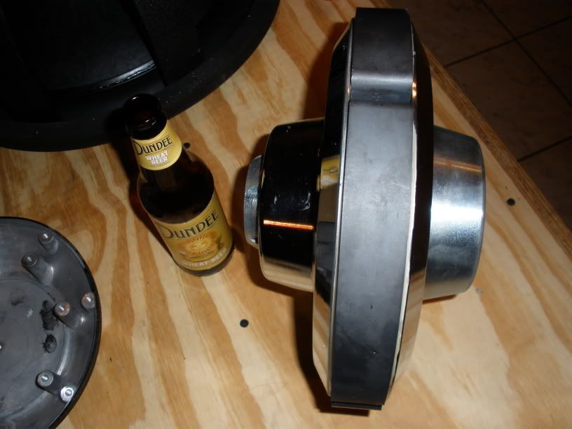
What is the driver in #460?
#542 is covered under a patent (US003983337) issued to Babb (expired), and does improve linearity with a small loss in small-signal efficiency.
http://www.google.com/patents?id=2oF8AAAAEBAJ&pg=PA6&dq=3983337&source=gbs_selected_pages&cad=4#v=onepage&q&f=false
#542 is covered under a patent (US003983337) issued to Babb (expired), and does improve linearity with a small loss in small-signal efficiency.
http://www.google.com/patents?id=2oF8AAAAEBAJ&pg=PA6&dq=3983337&source=gbs_selected_pages&cad=4#v=onepage&q&f=false
Last edited:


What is the driver in #460?]
RE Audio XXX 18 D2. 15" deep, 80lb boat anchor. AKA the bass pump.

They have almost similar overall max SPL’s when both used to their max power input. The 18 Sound pushes out about 1dB more then the RCF (in a 36Hz TH) throughout the bandpass except for < 45Hz. Under the 45Hz the RCF seems to have a little more output.
From an engineering point of view I would favour the 18Sound because it stays cooler (less power compression) under max load. If you compare motor to mass ratio they are very similar. Both use double spider suspension and only the 18Sound uses a double shortening ring system.
Soundwise most of my colleagues (me included) preferred the sound of the RCF but that’s personal. The RCF had a little less definition in the upper area but clearly sounded fuller in the lowest octave of the bandpass at max power. However the 18 Sound did sound less 'forced' at maximum power. But of course sound description is suggestive and very personal, I think.
We know that a well engineered balanced PA drivers should reach its Xmax at AES power rating. So in case of the 18Sound 18LW2400 with a Xmax of 9,5mm should be reached at 1200Watt (AES power rating). Lucky for us 18Sound (is the only brand who) shares power compression figures for their drivers. In case of the 18LW2400 it suffers from 2,2dB at AES full power (1200W).
We also know the Re of the driver which is 5 Ohm. If you use this calculator you can calculate Eg (HornResp Voltage Input parameter) 1200W at 5Ohm = 77,46V for this driver.
If you use Xoc1’s TH18 HornResp input as an example you will see at 1200 watt (77,46V) the excursion reaches 12,3482mm at 48Hz.

The real Xmax is however 9,5mm so we need to lower the excursion with 2.8482mm in the HornResp excursion Graph. With trial and error you can find out Eg needs to be set at approx 59,6V to reach 9,5mm. Use the same calculator again to find out that 59,6V and 5 Ohm means 710W

Now we can calculate how many dB’s the difference is between 710W and 1200W.
1200 : 760 = Factor 1,69
Use the following calculator to calculate the factor of 1,69 into dB's.
You will read 2,28dB. If you compare that to the factory specs given for power compression (2,2dB) you can see how close it is.
I know I'm a terrible teacher but I tried to make it as simple as possible without using difficult formula's...
I emailed rcf-usa and they kindly replied in regards to their LF18N451:
"Hi Justin,
the power compression at 0dB is 2.2dB and at -3dB is 1.2dB
Michele Begotti
Audio Systems Department
RCF S.p.A.
Via Raffaello, 13 - 42124 Reggio Emilia - Italy
Tel. +39 0522 274 411 - Fax: +39 0522 232 428
RCF - Homepage "
Food for thought and info for the computer 😉
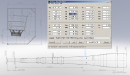
here is a mod of a model i posted earlier.
as djim sugested ,i put the magnet outside the chamber for better heat dissapetion.
the box is 570lts and is 1+ 2/3 of 4'x8'sheet ,so thats 60 kg (whitout bracing)

i like ur idea epa anyone had tested this plan yet? i only hate the high dimension. if it works fine. sometime ill downscale for 15" Drv and sometime the high dimensinsion will decrease a little. depth may be 70,it will ok.
the ideer was to lay the flat on the floor.i like ur idea epa anyone had tested this plan yet? i only hate the high dimension. if it works fine. sometime ill downscale for 15" Drv and sometime the high dimensinsion will decrease a little. depth may be 70,it will ok.
this model is only simmed, not bild
also have some symatric 15" moddels.
bit les high .i wil post it sometime later.
thanks epa if possible please u use this driver for model. im not good for bend the long horn. i ever try to bend with acad but rotate many sections and difficult too. if u finish the plan please PM me thanks again
P.Audio System Co., LTD
P.Audio System Co., LTD
I have done a quick sim on the B&C 18TBX100
Initial 1w response looks promising
If Xmax is 9mm then x-max is reached at just above 56V (400W /8R)
(no allowance for compression!)
Comparisons on charts
2.8v Grey PD1850 Black B&C TBX
Theoretical Xmax limited outputs Grey PD1850 @80V - 11mm Black TBX100 @ 56V 9mm
Please download Hornresp and feel free to compare other drivers yourself!😀
I have a sudden itch to try these***. They're on sale at PE. Someone give me some extra encouragement!
***But, in this:
Attachments
Last edited:
i just modeeled a tbx18 box for korrnylike
575 ltr netto 2 sheets.
looks good ,so many options justin.😛
575 ltr netto 2 sheets.
looks good ,so many options justin.😛
the p audio sims great in the same box,more or less the same as the b&c tbx 18 but 2 db less outputi like ur idea epa anyone had tested this plan yet? i only hate the high dimension. if it works fine. sometime ill downscale for 15" Drv and sometime the high dimensinsion will decrease a little. depth may be 70,it will ok.
im working on it in this topic
EPA
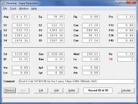
To clarify the point I asked the best way to simulate this in the Hornresp thread. (Post 1500)
http://www.diyaudio.com/forums/subwoofers/119854-hornresp-150.html
General consensus is that the coil resistance should be added to Rg, and the coil inductance added to Le...
This does make a difference.
Screenshot shows sim in post 21 with 4uH 0.72R inductor in grey and 2.5uH 0.38R inductor in black.
Maybe a tweak to the design is in order? Assuming that Crescendo hasn,t committed anything to a build yet! 😱
Was this comment directed to your design or epa's? I'm heavily leaning towards your 'Real 6 Fold' design (xoc1.m) and want to make sure it doesn't need anymore changes when loaded with a B&C 18TBX100. Did you ever post a cut-sheet? I searched and found a schematic, but no cut-sheet. I can get 5x5 3/4" void-free birch for $55US. 4x8 sheets cost quite a bit more here.
Attachments

Last edited:
i just modeeled a tbx18 box for korrnylike
575 ltr netto 2 sheets.
looks good ,so many options justin.😛
Your enclosure looks very nice epa!
 Did you use SketchUp for that or something similar?
The response of this design sims VERY close to Xoc1's 'Real 6 Fold' TH with the same driver. Yours requires more wood cuts and appears slightly more time consuming, but is slightly smaller.
Last edited:
hi justin
i think this was about the discusion of putting a/wich coil in series of the bms driver.
the point xoc1 was making that by adding a coil you also add resitance,wich in turn does the opposite of what the higher le vallue does to the responce.
in the meantime ive learnt that for subs you can double the le vallue wich is measured @ 1khz
so adding a coil is almost always not needed.
what i like about the tbx box,is that it has little volume lost(waist space)only 2 corners and a bit at the handle/top
most of the th's will work great as long there is consistancie .
why not try moddel something yourself,i could assist you.
regards erik
I'm heavily leaning towards your 'Real 6 Fold' design (xoc1.m) and want to make sure it doesn't need anymore changes when loaded with a B&C 18TBX100. Did you ever post a cut-sheet? I searched and found a schematic, but no cut-sheet. I can get 5x5 3/4" void-free birch for $55US. 4x8 sheets cost quite a bit more here.
Hi Crescendo
I never got around to modelling up all the panels for this design, but here are all the relevant dimensions if you want to make sawdust 🙂
Regards
Martin
Attachments
hi crescendo.
if you have the side pannels cut,take a ruler and draw al the inside pannels on it.
you can check/measure all pannels ,and you can pre-dril the holes,put nails left and right of lines so pannels stay in positsion when you screw them tight.
use the brown expanding glue then you dont need to close the gaps afterwards.
greetz erik
i did a qiuck sketchup.
left side would become 120x85x45
it has an advantidge of a nice frontal area in a stack of 3(see left bottem)
right bottem is standart fold ,85x85x65
right top is with a chamber(have to model that ,but i remeber it worked with the 3015lf)120x65x60.
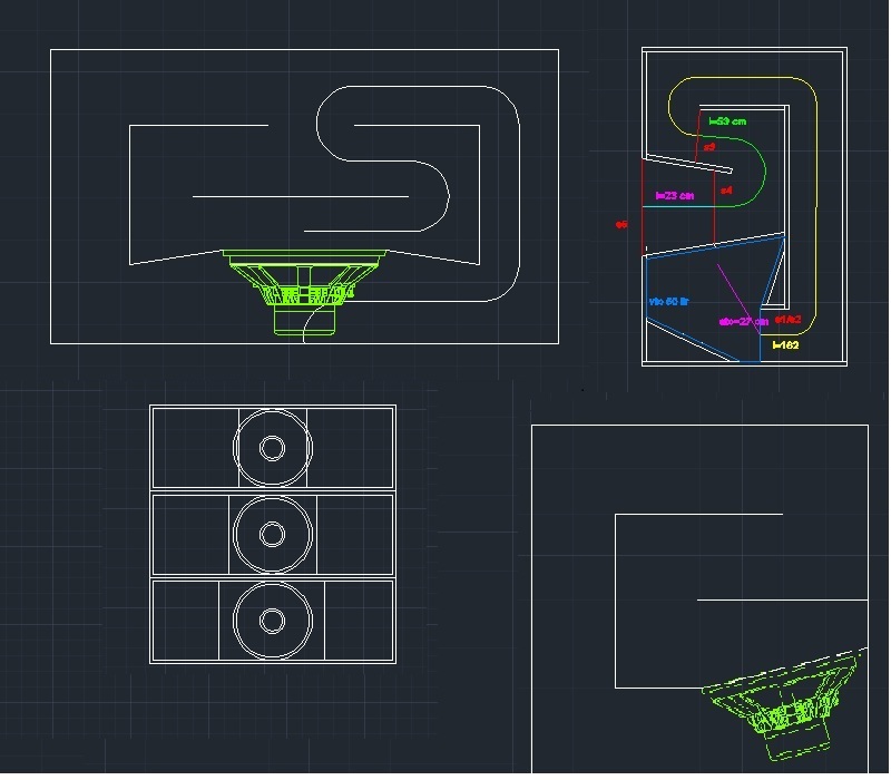
all sketshups so the end result could differ a bit.
left side would become 120x85x45
it has an advantidge of a nice frontal area in a stack of 3(see left bottem)
right bottem is standart fold ,85x85x65
right top is with a chamber(have to model that ,but i remeber it worked with the 3015lf)120x65x60.
all sketshups so the end result could differ a bit.
Last edited:
- Home
- Loudspeakers
- Subwoofers
- C/E/X PA Flat to 30 (FT30) PA TH Awesomeness