Combined with 19,05mm (0,75") that gives a calculated Xmax of 4,89mm.
(Somehow I think it should be something like 5.5mm)
(Somehow I think it should be something like 5.5mm)
Last edited:
here is a mod of a model i posted earlier.
as djim sugested ,i put the magnet outside the chamber for better heat dissapetion.
the box is 570lts and is 1+ 2/3 of 4'x8'sheet ,so thats 60 kg (whitout bracing)

as djim sugested ,i put the magnet outside the chamber for better heat dissapetion.
the box is 570lts and is 1+ 2/3 of 4'x8'sheet ,so thats 60 kg (whitout bracing)
Interesting results Epa 
Your design is based on (1/3wavelength) Fb of ???? (32Hz?)
While Xoc1-TH18 is based on a Fb of 3.045m = 37.6Hz
Your design has a significant increase in low end extension at cost of a relative high Group Delay at the highest excursion point and at costs of bandpass in the higher part of the frequencies.
The question is will it perform as your prediction...
Last edited:
wel the goal was ,low towards 30 hz with resenable output,and not to heavy.
the group delay is not so good ,needs to be crossed 80~90 hz.
i can't see a reason why it shoulden't work(mayby relative short path towards the mouth?)
what about un-even loading would that be a problem?
it begins and ends as a single fold would,just some bends in the middle sector😀
btw i recalculated hr inputs more precise above.
i think it needs reflectors @ bottem front.
it needs some tweaking to get concistancy
the 18lw 2400 preforms equaly in this design.
Last edited:
oops😱 i just discoverd a flaw,needs to be corrected
ill adjust shortly
edit/ adjusted
ill adjust shortly
edit/ adjusted
Last edited:
...what about un-even loading would that be a problem?
it begins and ends as a single fold would,just some bends in the middle sector😀
btw i recalculated hr inputs more precise above...
Hi epa,
I think your design is better than many other multi-folded seen here:
IMO,multi folds in a PA speaker is a SQ disaster when compression levels are reached.
it needs some tweaking to get concistancy
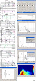
?, See a simulation that reflects your HR input data:
b🙂
Attachments
thanks bjorno.
i discovered a flaw and its corected now above.
maybe i have to make the box a few cm's deeper to get bigger s1 and s2(dont want to take it out s4😛
i discovered a flaw and its corected now above.
maybe i have to make the box a few cm's deeper to get bigger s1 and s2(dont want to take it out s4😛
Mission accomplished!wel the goal was ,low towards 30 hz with resenable output,and not to heavy.
Indeed, the 35Hz peak is a little high (+30ms) and thethe group delay is not so good ,needs to be crossed 80~90 hz.
peak at 150Hz, although very small band so that might be much better in reality (less high).
Indeed, if the driver is going to 'see' the path like a more traditional TH concept the sound will start to roll of 10Hz higher.i can't see a reason why it shoulden't work(mayby relative short path towards the mouth?)
For cheap drivers it can be a problem but in an age of double spider techniques, high cone stability and exotic materials I don't think that will be a problem.what about un-even loading would that be a problem?
That's the reason I had to try another driver and sure the outcomes look very niceit begins and ends as a single fold would,just some bends in the middle sector😀 btw i recalculated hr inputs more precise above.
In the first 1/6 of the total path I should use corner correction in every corner.[/QUOTE]i think it needs reflectors @ bottem front. it needs some tweaking to get concistancy
It sure does!the 18lw 2400 preforms equaly in this design.
thanks bjorno.
i discovered a flaw and its corected now above.
maybe i have to make the box a few cm's deeper to get bigger s1 and s2(dont want to take it out s4😛
i discovered a flaw and its corected now above.
maybe i have to make the box a few cm's deeper to get bigger s1 and s2(dont want to take it out s4😛
Sorry, that should be 1/3 of the total length... 😱In the first 1/6 of the total path I should use corner correction in every corner.
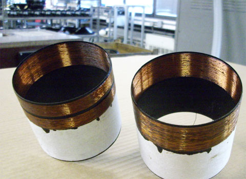
B&C's split-winding technology
After contacting B&C about their split-winding technology they send me a picture. On the left side a voice-coil with Split-Winding technique and on the right side a voice-coil with 'normal' winding. On my question, if or how the gap in the split-winding influences the Hvc figure, B&C answered;
"The height of the voice coil is the distance from the first to the last turn of wire. Even with the split coil technique, this distance is equal for the inside (full) layer and the outside (split) layer."
Attachments
Last edited:
intresting.
what is the advantage of a split vc?
edit/ reduce distrtion and non linieraties. but how :?
what is the advantage of a split vc?
edit/ reduce distrtion and non linieraties. but how :?
Last edited:
The PDF explains a little, but in short: higher excursion/lower THD.
Edit after your edit 😉
Take for instance the 18SW115:
Xmax calculated [(Hvc-Hg):2] = 10mm
Xmax 10%THD = 14mm
Xvar 50%BL or 50% Cms = 16mm
If you would take out the 'split' it would be guestimated:
Xmax calculated = 9mm
Xmax 10%THD = 12,8mm
Xvar 50%BL or 50%Cms = 14,5mm
Edit after your edit 😉
Take for instance the 18SW115:
Xmax calculated [(Hvc-Hg):2] = 10mm
Xmax 10%THD = 14mm
Xvar 50%BL or 50% Cms = 16mm
If you would take out the 'split' it would be guestimated:
Xmax calculated = 9mm
Xmax 10%THD = 12,8mm
Xvar 50%BL or 50%Cms = 14,5mm
Last edited:
my first ideer was that the more the windings are out of the gap the less heat dissapation.
but indeed when it matters they are more in the gap now.
clever stuff😀
but indeed when it matters they are more in the gap now.
clever stuff😀
Awesome! Thanks for that Djim.
I had wondered whether this was a split coil linear motor implementation and it appears that it is. Split coil is public domain with no enforced patent. It is sort of odd that they would utilize it here when the xmax is easily attainable with regular over or underhung. Split coil penalizes peak bl but provides a broad flat plateau. I had a hunch this was the case as soon as I saw the Klippel data from their 18sw115. I have never seen an arrangement such as theirs with an inside outside wind and a split coil on only the outer wind. Intriguing.
I had wondered whether this was a split coil linear motor implementation and it appears that it is. Split coil is public domain with no enforced patent. It is sort of odd that they would utilize it here when the xmax is easily attainable with regular over or underhung. Split coil penalizes peak bl but provides a broad flat plateau. I had a hunch this was the case as soon as I saw the Klippel data from their 18sw115. I have never seen an arrangement such as theirs with an inside outside wind and a split coil on only the outer wind. Intriguing.
Over-hung -> higher thermal power compression figures or massive increase of VC weight
Under-hung -> lower Xmax or lower sensitivity and non-linearity’s rise more rapid as soon the coil starts leaving the gap.
Split-Wire -> low pwr comp figures, just a fraction less sensitive in favour of high Xmax (10%THD) and high Xvar (50%BL or 50%Cms).
Under-hung -> lower Xmax or lower sensitivity and non-linearity’s rise more rapid as soon the coil starts leaving the gap.
Split-Wire -> low pwr comp figures, just a fraction less sensitive in favour of high Xmax (10%THD) and high Xvar (50%BL or 50%Cms).
Eminence 3015LF
An externally hosted image should be here but it was not working when we last tested it.
Nice picture Dan Any idea if it is the old or the new version?
Edit: after expanding the picture I found a ratio of approx 1 : 3 (Hg : Hvc)
Any idea if it is the old or the new version?Edit: after expanding the picture I found a ratio of approx 1 : 3 (Hg : Hvc)
Last edited:

- Home
- Loudspeakers
- Subwoofers
- C/E/X PA Flat to 30 (FT30) PA TH Awesomeness