Sure, as long as it is a neutral person conducting the tests. Do you want to have negative results questioned by me and others because the impartiality of the tests were questioned. If you are so sure that the tests can be done in an impartial way then why not let someone else do the testing? Then if it turns out in favor or you and against me all the better for you. I and others will not be able to complain. And I assure you I would in the first situation and I wouldn't in the second. That's a promise.
Again. The whole point of a controlled test is to avoid any impact of partiality, avoid bias. Both SY's and yours, and anyone's. Please.
jd
But, when it comes to Bybee, he had plenty of input potential from me, including real devices.
You were indeed kind enough to show me the devices and (if memory serves) showed me a disassembled one. But I don't recall any offer to let me test them. And the test data you've offered up so far is so incomplete and non-understandable, it seems incumbent on me to get out something more complete and (here's that word again) reproducible.
Or perhaps they achieve more gain??
Actually, copper does not exhibit any superconductivity, even in superfluid.
The best one can hope for is three orders of magnitude better than room, and that is 7 nines annealed to within an inch of it's life.
Cheers, John
I would say that was "near" enough. Does eutectic solder ever superconduct? I would think staying near over a wide temperature range would be yet another amazing property.
Last edited:
But one must not change ANYTHING by test setup. Any change of wires, switches etc. is UNACCEPTABLE. It automatically means change of RF, EMI, and such a test is USELESS then.
Give me some suggestions on how you'd do that, John, and I'll be happy to give it a fling.
Done.
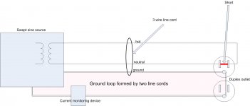
The pink area is the ground loop which will intercept the line cord flux. Any variation of the external inductance of the line cord will result in a change in the coupling here. Measurement of the ground loop current is measuring the inductive coupling which will impact the reference ground integrity of a single ended audio system, and the currents through a chassis can even upset the internal path integrity of a balanced differential input system.
edit: one could easily break the loop conductivity and substitute a dvm for the current probe, changing it to a high impedance/voltage measurement...but for most systems, the loop is low impedance, and the loop current does fight the flux, consistent with Lenz's law..
I would say that was "near" enough. Does eutectic solder ever superconduct? I would think staying near over a wide temperature range would be yet another amazing property.
Depends on which eutectic.
Lead tin eutectic is avoided when soldering two superconductors together, as lead has a superconducting region below 9 Kelvin. The accelerator guys prefer to have more control over the current distribution through a lap joint, as the current density through the joint is 10e3 to 10e4 amperes per square mm. Current density "anarchy" in that realm generally has a very high price tag..
edit: ah, important point...The evolution of a soldered joint with copper starts with the formation of two different alloys of copper/tin. During this process, the lead gets left behind without a "date" so to speak.. this is the lead that is available for the messing up of the current distribution...
Eutectic tin/silver does not have a superconducting regime, so is the solder of choice for all superconducting joining, be it MRI's, antimatter confinement, or particle accelerators.
As to staying "near", all that is happening is a temperature dependency on the mean free path of the electrons in the lattice. Extremely pure copper with few dislocations will simply have a mean free path that can extend in to the centimeter range..but this isn't superconductivity as there is still a wire voltage gradient with electron acceleration and collisions with the lattice....just not as many. And at room temperature it will be extremely difficult to tell the difference that will occur in liquid helium.
Cheers, John
Attachments
Last edited:
One gets the appearance that everytime someone in the forum reports hearing something that can not be readily explained by the Engineers of the forum, that they are quickly made to feel sorry that they ever bothered posting.
This is exactly as it should be. The engineers form a quorum. No-one among them can carry an argument unsupported, and no unsupported argument can succeed in the critical atmosphere provided by the quorum.
The forum is already plagued with numerous posters entirely too uncritical of their own views. These are often expressed in terms of the utmost confidence, and are likely to misinform casual, incautious or less-well-educated readers. If posters subjected their own material to more rigorous examination before committing to the 'Submit Reply' button, detailing the alternate explanations they have considered and preferably rejecting for themselves those that require a complete re-write of modern physics, then when a genuine unusual phenomenon was reported there would be less likelihood of it being rejected out-of-hand by people who have become accustomed to being bearded by others whose most outstanding characteristic is a desire to argue with some individual better qualified than they are.
Such posters frequently have a facility for stretching semantics and prolonging disagreement, affording satisfaction to nothing but their own sense of self-importance, to a point beyond where they would normally be constrained in a face-to-face confrontation by the risk of a punch to the nose. Any reader might imagine that the entire point is to disagree. This situation comes about because engineers constrain themselves to language such as 'very probably', whereas their opponents have no compunction whatsoever in employing absolutes.
If a poster finds that their ideas are rejected by a number of other posters with established technical reputations, this is the time to reconsider, not to dig in one's heels and start to turn over rocks in search of a conspiracy.
In fact there is at least one U.K member who is downright rude and sarcastic, but never appears to earn a reprimand,or banning from the forum like G.K. and a few others have been.
When I see that a poster has moved past reasonable argument, then I am happy to use other techniques to discredit them.
As regards rudeness, many of these posters think nothing of impugning the intellects, integrity and technical competencies of members merely in passing, with comments about 'closed minds', or suggestions that their handling of evidence might be less than honest. Asides such as these are evidence that such individuals can only aspire to the standards of morality which are expected as a commonplace of the professional engineer. Chartered engineers have a status in law, in the UK at least, insofar as, just like a GP, they are trusted to countersign passport photographs and undertake other minor legal functions. In such circumstances more robust insults are not only more honest and direct (being seen to be 'fair comment', pandora's box having been opened) but also go some way to redressing the imbalance that engineers' natural reluctance to take up hard-and-fast positions inflicts on them, making the reality of the situation more readily comprehensible to readers less well versed in the technical niceties (everybody knows what a moron is).
w
 Let's stick the subject at hand please.
Hi John,
Huh?
Always remember that we have varying levels of experience among our members. Like any manual, some things require repetition. Personally, I didn't think I overdid that. You got the message. 🙂
Hi jneutron,
If I haven't said this out loud, I am acutely aware that you are more than competent on the bench. I don't doubt your methods either, never have.
-Chris
Huh?
Always remember that we have varying levels of experience among our members. Like any manual, some things require repetition. Personally, I didn't think I overdid that. You got the message. 🙂
Hi jneutron,
Well - yeah. I said that.For some perhaps. Not for me.
If I haven't said this out loud, I am acutely aware that you are more than competent on the bench. I don't doubt your methods either, never have.
Good lord man! No way was I going to go there without a ton of explanation. This is a can of worms on the wrong bench! 🙂What about a ground loop coupling/susceptibility test?
🙂 What can I say? Is it possible that that system has mutually exclusive terms in it's definition?I assume the end use system design will be code compliant and single ended drives..
I have nothing available that will generate that unless I build it. SY doesn't either unless he wants to torture an amplifier. Nelson could help there I think.I'd recommend running a swept sine 1 ampere current out to 50 Khz through the line cord
And there's the rub. Given a current source with known characteristics. SY has a 3468A as I recall and I can't remember if it has the sense terminals for resistance measurements. He would have to rely on null only.Given a current source and a 34401
I'd run the current into the leads further out. Then you could use the sense contacts at a known distance as you suggested. How many of us can position these contacts to a distance known to the width of a razor blade? Copper bar contacts might be a better plan though, otherwise you'll want to null any contact potential out or keep the temperature constant across the jig. See, now you're the one getting fussy about everything! 🙂To control this, I'd make a test fixture that uses a pair of razor blades for the v probes, and lock them dimensionally such that they are one fixed distance apart, with the current clips outboard of the blades.
Possibly to us here, but being prepared for a possible challenge to any of the test data in an effort to discredit the testing should be expected. Other than that, the actual reading is only academic.The test is not pass/fail. It is value only.
-Chris
Chris, a 1 amp current with swept sine (or better yet, MLS/impulse) won't be too hard to cob together. And fortunately, I've been doing Kelvin measurements since grad school. 😀
I like the pro RF lab stuff. Look in the GigaHz. Think cavity resonator. I could be wrong on this, but some devices have textbook dimensions. In this case, if anyone can find an engineering textbook describing one, look for a CAVITY RESONATOR...... Should that be a cavity resonator (electromagnetic UHF resonator) - what frequency tuned at, for what reason?
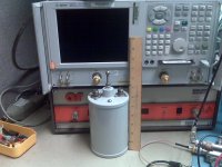
No need to Google, I have a lab full of them. This one covers 850 to 870 MHz. The one for 150 MHz is 3 feet tall. Cavity resonators typically use air for the dielectric medium hence the name cavity. It is possible to substitute a material with a high dielectric constant for the air in order to reduce the physical size. These are usually called dielectric resonators (or some other trade name). In any case a device capable of resonance near the audio band would be huge, semi trailer sized at least. A dielectric resonator using state of the art material for 150 MHz would be about 2 inches long.
If there is any resonance at all in the range of 100 KHz to 8.5 GHz, the network analyzer shown behind the cavity resonator will find it! Is a resonant device in the GHz region of any use to audio when the interconnecting cables are not capable of passing frequencies above sa few tens of MHz on a good day? Maybe....
Chris, although audio gear won't pass gigahertz signals, the gear can be affected by them. One thing I like to do to test the immunity of my designs is to do some cell phone dialing in different spots near the unit. It's a crude test, but it's a real-world situation.
Yes, it is a crude test, but one I routinely do. Our world used to be polluted only by 60 Hz. In the last few years we have infiltrated almost every aspect of our lives with RF radiation reaching up to about 5.7 GHz in our homes and 10.5 GHz outdoors. A well designed audio device should be immune to reasonable levels of RF radiated into the device, or conducted in through the audio, power, or speaker cables. A GSM (ATT or T-mobile) or iDEN (Nextel or Telus) phone is worst case since the RF is pulsed on and off at an audio rate.
The power lines used to handle 60 Hz (USA) with a few lower order harmonics. Our Power company used to claim 3% distortion maximum from the wall outlet. Today I measure 10+% in the evening when AC units are humming and TV sets are glowing. There is visible flat topping on the sine wave. Late at night it is still over 5%. The switching power supplies and X10 devices pump garbage back into the power lines up into the MHz range. I am not even mentioning BPL. I use the electric drill test to find a poor design here. Plug a corded electric drill into the same power outlet as the audio system and pull the trigger. Hear anything? If so fix it! Low level crud that is not quite audible can still "cloud the issue" and use up downward dynamic range.
How do you fix these issues? Usually by adding filtering to the interconnects of a system, including the power input. If this is the principle that the Bybee device uses, then it may have an audible impact on the system. It it the most economical way to solve the issue? Well that depends on your budget. Will they have an impact on a system that is already hardened against these threats? NO! Is any DIY system perfect against EMI? Not many. Affordable commercial equipment? No chance!
If the Bybee device works in this fashion we should be able to see it. If it makes an audible difference at all, we should be able to see it under test. Do I have a biased opinion? Don't we all. Would I like to find a "device" that made my system sound better for $100 or $200? Yes, If I could hear it, I might even buy it. Am I a skeptic? I am an engineer aren't I? If I can't hear it in my system is the device useless to other people? No. As it has been pointed out, my speakers are not the best and my hearing sucks. I had a customer reliably identify his Mullard 5AR4 in an amplifier that I built for him, when I could not. This was a Tubelab SE through headphones, using my CD player. There were about 6 different tubes, mostly cheap stuff. I would have never believed that this was possible until I set up the test.
Attachments
Hi George,
You should hear what a cell phone does to some phone systems. And yes, the pulsed nature of the RF amp makes it far more audible beyond the digital errors it creates.
The HP 8640B claims to use a tuned cavity resonator to achieve it's lowish distortion. At the time it was low anyway. It's a substantial thing, but simple in concept. I wonder what temperature correction is like with those? I'd be tempted to heat the whole mess up to some fixed temperature similar to an oven for a crystal. Today they are using solid state means to generate cleaner signals aren't they?
Nice amp BTW. Outta my budget by a long shot, not that I need that much power.
Gee, I thought I was one of the few that used the drill test. And yes, most consumer audio items are not immune, not even close. Maybe the power supplies are so poorly designed that they can benefit from those special power cords and such.
Thinking on the amp you designed where the customer can hear the tube differences, is anything fed from the first or second filters? Or is it a case that the lower impedance tubes have lower voltage drop and varying hash levels? I have no idea what your power supplies look like George, so I can only guess. If anyone can really hear a difference, there is something there that can be measured. It just might not be what you'd expect to find as the cause. If the amp is single ended, there is more chance of the rectifier being heard. Sometimes it has more with knowing what to listen for than the quality of hearing you have.
Hey SY,
You didn't answer my question though. I'm not wanting to look ap the manual or a picture of the 3468A to see if it is capable of the four terminal (Kelvin - happy John? 🙂 ) connections. I guess I'll "Google it".
... Ah ha! Yes it does. The front panel is very similar to the 3478A meters - cool. That's the meter you have, isn't it?
-Chris
You should hear what a cell phone does to some phone systems. And yes, the pulsed nature of the RF amp makes it far more audible beyond the digital errors it creates.
The HP 8640B claims to use a tuned cavity resonator to achieve it's lowish distortion. At the time it was low anyway. It's a substantial thing, but simple in concept. I wonder what temperature correction is like with those? I'd be tempted to heat the whole mess up to some fixed temperature similar to an oven for a crystal. Today they are using solid state means to generate cleaner signals aren't they?
Nice amp BTW. Outta my budget by a long shot, not that I need that much power.
Gee, I thought I was one of the few that used the drill test. And yes, most consumer audio items are not immune, not even close. Maybe the power supplies are so poorly designed that they can benefit from those special power cords and such.
Thinking on the amp you designed where the customer can hear the tube differences, is anything fed from the first or second filters? Or is it a case that the lower impedance tubes have lower voltage drop and varying hash levels? I have no idea what your power supplies look like George, so I can only guess. If anyone can really hear a difference, there is something there that can be measured. It just might not be what you'd expect to find as the cause. If the amp is single ended, there is more chance of the rectifier being heard. Sometimes it has more with knowing what to listen for than the quality of hearing you have.
Hey SY,
I didn't thin I had to mention that fact that I didn't have any doubts where you are concerned in addition to my earlier comments. Never any doubt my friend.And fortunately, I've been doing Kelvin measurements since grad school.
You didn't answer my question though. I'm not wanting to look ap the manual or a picture of the 3468A to see if it is capable of the four terminal (Kelvin - happy John? 🙂 ) connections. I guess I'll "Google it".
... Ah ha! Yes it does. The front panel is very similar to the 3478A meters - cool. That's the meter you have, isn't it?
-Chris
Chris, I'm at my office so couldn't check the model number. Whatever I have, it's not set up for Kelvin measurement- when I've needed that, I just rig something up myself.
Funny about the drill test. I stumbled on it by accident, using a drill plugged into the audio power circuit. It played hell with the long AES/EBU digital line I had going. That's when I put a transformer in the digi line. Helped a lot. So did better grounding.
Hi John,
Most test equipment will easily cover up to 1 MHz. Even though many older HP THD meters may only cover up to 100 KHz fundamental, their response does include 1 MHz as a rule. They will cover and respond to harmonics in that range. A 3586B Selective Voltmeter is good up to 20 MHz anyway, if memory serves.
At any rate, this is easily tested. This range is something I would normally include anyway. I'm pretty sure most people here would also
-Chris
Are you suggesting that the device affects stuff like HF hash? Could be, and this would certainly not considered by many audio technical types from the bad old days.You might have to go higher, at least from my estimations.
Most test equipment will easily cover up to 1 MHz. Even though many older HP THD meters may only cover up to 100 KHz fundamental, their response does include 1 MHz as a rule. They will cover and respond to harmonics in that range. A 3586B Selective Voltmeter is good up to 20 MHz anyway, if memory serves.
At any rate, this is easily tested. This range is something I would normally include anyway. I'm pretty sure most people here would also
-Chris
Hi SY,
Darn. Sorry about that, sounds like a 3466A. I'll keep my eyes open in that case. It's good to 1 KV at least, isn't it?
Just a note. Most meters of that age use a non-rechargeable lithium battery that should be dying right about now. I know the replacement part, could you replace it yourself? You should use two batteries so the cal constants don't dump. You would appreciate a 34401A, but the 3478A is a really good meter as well. Keep in mind these are only good for 300 VDC max. Keep the other for sure. If you see a 34401A heading for the dump, grab it!! If you're lucky enough to run into a 3458A, send it here!
-Chris
If some of you would ONLY Google 'microwave cavity resonator', many questions directed toward me would become clear. I suspect 15-30 gHz is an important measurement. This is based on the Volume of the devices.
I suspect 15-30 gHz is an important measurement.
Maybe we should look at infrared? Ultraviolet? Infrasonic? Psychotic? Keep tossing them out there, maybe something will stick.
The devices arrived today. First evaluation was from my wife: "$180??? You ****ing gotta be kidding!"
- Status
- Not open for further replies.
- Home
- General Interest
- Everything Else
- Bybee Quantum Purifier Measurement and Analysis