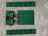
Very nice Boards !
I have the same and can offer two sets from my first build.
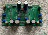
Assembled with Takman Resistors, Nichicon Caps, Bourns Trimmer.
Soldered with Wonder Solder 😉
I disassembled the JFETS and MOS for my second build.
One Set 100€ for EU Builders.
Daniel
I have the same and can offer two sets from my first build.
Assembled with Takman Resistors, Nichicon Caps, Bourns Trimmer.
Soldered with Wonder Solder 😉
I disassembled the JFETS and MOS for my second build.
One Set 100€ for EU Builders.
Daniel
Attachments
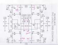
Probably the wrong place to insert this but here goes...I am building a pair of BA3 B mono blocks and am just checking ups on the adjustment process fro the front end to see whether it uses the same points as the regular version. Attached are the schematic which combines R5 and shows the measuring points, as well as the chassis and some resistor mods take adjustment easier....any advice from anyone who has built the mono blocks welcome
Attachments

I have built some balanced BA3 monoblocks (complimentary boards). I set bias and offset before bridging R5 on the FE. I am hearing motorboating on the outputs 🙁
Music comes through fine and doesn't sound distorted, but the motorboating is quite intense. It is a "putt putt putt putt" low frequency/bass sound.
It happens with both my DIY PSU and my benchtop PSU.
When I slowly turn up B+ (either with variac and DIY PSU or benchtop psu) the frequency of the motorboating increases (i.e. the putt-putts get closer together in time).
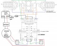
Attached is a schematic of what I'm working with. Last night I tried adding the ground-loop-breaker circuit with another GBPC3510 and the CL60 but that didn't help. Not surprised it didn't help though, as I don't think this is the PSU's fault.
The motorboating persists even when the FE is disconnected from power, so i'm thinking it's likely something with the output stages.
Hoping you pros have some ideas and/or next steps for troubleshooting? I do not have an oscope, but maybe I need to just man-up and buy one already.
Music comes through fine and doesn't sound distorted, but the motorboating is quite intense. It is a "putt putt putt putt" low frequency/bass sound.
It happens with both my DIY PSU and my benchtop PSU.
When I slowly turn up B+ (either with variac and DIY PSU or benchtop psu) the frequency of the motorboating increases (i.e. the putt-putts get closer together in time).
Attached is a schematic of what I'm working with. Last night I tried adding the ground-loop-breaker circuit with another GBPC3510 and the CL60 but that didn't help. Not surprised it didn't help though, as I don't think this is the PSU's fault.
The motorboating persists even when the FE is disconnected from power, so i'm thinking it's likely something with the output stages.
Hoping you pros have some ideas and/or next steps for troubleshooting? I do not have an oscope, but maybe I need to just man-up and buy one already.
Attachments
everything is ........ somewhere
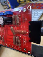
Hi Zen, this means we just take the output + and - terminals to speakers without grounding from the power boards..... but then are the 2 signals not in opposite phase to each other? Will they not null out into the speakers? I am sure I am missing something, but then I have just started understanding bit about balanced circuits
The two red output terminals become Speaker + and Speaker -. The speaker does not attach to amplifier ground.
The output section attached to +in is speaker positive.
The output section attached to -in is speaker negative.
I think I fired my question first to Zen, but rewriting since this seems to be addressed now...are the two signals not at 180 deg to each other ? will they not nullify at the speakers? Apologies in advance if I sound like a noob.
They are 180 from each other. That’s the point.
As the signal goes positive the speaker goes out. As it becomes negative it is pulled back. Music is AC. 🙂
As the signal goes positive the speaker goes out. As it becomes negative it is pulled back. Music is AC. 🙂
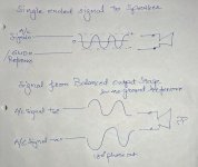
Ok, point taken audio signals are sine waves/AC, but are they not referenced to the ground to take the swing, which translates to speaker movement depending on the polarity of the signal. In this case the 2 signals are 180 degrees apart...let me see if my upload works, tried to put a graphical representation...sorry used freehand
Attachments
kpsthatkur - I had very similar questions awhile ago. It took me quite some time to visualize and figure out.
Firstly, I think you and I had the same thoughts. One key thought helped me over the bridge to understanding.
The speaker reacts to the difference in potential between the two ends of the voice coil.
For a thought exercise assume: 1V => 1mm cone movement.
I have to think of finite moments in time => AC as modulated DC
In the diagram below:
Comments, criticisms are welcome. I will never say that I "know this". I just hope I'm starting to grasp the fundamentals.


Firstly, I think you and I had the same thoughts. One key thought helped me over the bridge to understanding.
The speaker reacts to the difference in potential between the two ends of the voice coil.
For a thought exercise assume: 1V => 1mm cone movement.
I have to think of finite moments in time => AC as modulated DC
In the diagram below:
At the positive voltage peaks of the red waveform, cyan is most negative. Positive red minus negative cyan => bigger positive. Same vice versa.
Assume the peaks on each of the red and cyan are +-10V
At the red positive peak, the speaker "sees" a 20V difference in potential from one side of the coil to the other. Which way does the driver go? Let's assume if the "red side" positive terminal is more positive than the "blue side" negative terminal; the cone moves outward. 20mm outward movement.
At the cyan positive peak, there is also a 20V difference in potential from one side of the coil to the other. However, now the "red side" positive terminal is less positive than the "blue side" negative terminal. So, the current flows the opposite way, and the cone moves the opposite direction => 20mm inward movement.
If you pick any point along the graphs, you can imagine how the coil will move, but the voltage differential will always be double due to the inverted waveform. The zero crossing is also timed perfectly.
This may also help to visualize DC offset. Imagine if the red and cyan plots were "shifted" upward or downward independently from one another.
I am sure I got details woefully incorrect, but I hope I got the first principles correct, and that the explanation makes sense.Assume the peaks on each of the red and cyan are +-10V
At the red positive peak, the speaker "sees" a 20V difference in potential from one side of the coil to the other. Which way does the driver go? Let's assume if the "red side" positive terminal is more positive than the "blue side" negative terminal; the cone moves outward. 20mm outward movement.
At the cyan positive peak, there is also a 20V difference in potential from one side of the coil to the other. However, now the "red side" positive terminal is less positive than the "blue side" negative terminal. So, the current flows the opposite way, and the cone moves the opposite direction => 20mm inward movement.
If you pick any point along the graphs, you can imagine how the coil will move, but the voltage differential will always be double due to the inverted waveform. The zero crossing is also timed perfectly.
This may also help to visualize DC offset. Imagine if the red and cyan plots were "shifted" upward or downward independently from one another.
Comments, criticisms are welcome. I will never say that I "know this". I just hope I'm starting to grasp the fundamentals.
I'm not sure if there is a separate thread for the balanced pre by itself, but there's been a lot of discussion here for both SE and balanced. Most of this thread has covered speaker amp builds.
The BA-3 as preamp build guide
FWIW - In various balanced pre-amps, I've used: 4-gang alps, dual TKDs for independent controls per channel, relay-stepped, and I'm getting ready to try Muses.
The BA-3 as preamp build guide
FWIW - In various balanced pre-amps, I've used: 4-gang alps, dual TKDs for independent controls per channel, relay-stepped, and I'm getting ready to try Muses.
kpsthatkur - I had very similar questions awhile ago. It took me quite some time to visualize and figure out.
Firstly, I think you and I had the same thoughts. One key thought helped me over the bridge to understanding.
The speaker reacts to the difference in potential between the two ends of the voice coil.
For a thought exercise assume: 1V => 1mm cone movement.
I have to think of finite moments in time => AC as modulated DC
In the diagram below:
At the positive voltage peaks of the red waveform, cyan is most negative. Positive red minus negative cyan => bigger positive. Same vice versa.I am sure I got details woefully incorrect, but I hope I got the first principles correct, and that the explanation makes sense.
Assume the peaks on each of the red and cyan are +-10V
At the red positive peak, the speaker "sees" a 20V difference in potential from one side of the coil to the other. Which way does the driver go? Let's assume if the "red side" positive terminal is more positive than the "blue side" negative terminal; the cone moves outward. 20mm outward movement.
At the cyan positive peak, there is also a 20V difference in potential from one side of the coil to the other. However, now the "red side" positive terminal is less positive than the "blue side" negative terminal. So, the current flows the opposite way, and the cone moves the opposite direction => 20mm inward movement.
If you pick any point along the graphs, you can imagine how the coil will move, but the voltage differential will always be double due to the inverted waveform. The zero crossing is also timed perfectly.
This may also help to visualize DC offset. Imagine if the red and cyan plots were "shifted" upward or downward independently from one another.
Comments, criticisms are welcome. I will never say that I "know this". I just hope I'm starting to grasp the fundamentals.
View attachment 901622
First pass, I tried a simple experiment with my balanced out on headphone amp . I connected +hot -cold > to > L channel, GND on a test headphone (which ofcourse is single ended) and then tried it with R channel, GND combo, unfortunately I could not hear any sound, not sure if it was due to internal signal processing circuit...but will try few more things soon
Fantastic experiment. Thank you for sharing. I've never done that.
I shamelessly stole the diagram, but I'll take responsibility for posting it if it's wrong. It's very similar to what I used when I was trying to figure all this out.
The best way for me to know I'm wrong is to post something to an internet forum. Someone much smarter than I is always around. 🙂 🙂
I'd love to make sure I really understand this also, or if I've been completely mistaken.
Edited to add - If you're up to it.
Does connecting pin 1 to (HP -) and pin 3 to (HP +) make music?
Does connecting pin 1 to (HP -) and pin 2 to (HP +) make music?
Edited to add (again): Sorry! With HPs, balanced 4-pin connections to the amp. You know what you're doing. They don't have a GND. Just two hots and two colds. Ignore me Apologies.
I shamelessly stole the diagram, but I'll take responsibility for posting it if it's wrong. It's very similar to what I used when I was trying to figure all this out.
The best way for me to know I'm wrong is to post something to an internet forum. Someone much smarter than I is always around. 🙂 🙂
I'd love to make sure I really understand this also, or if I've been completely mistaken.
Edited to add - If you're up to it.
Does connecting pin 1 to (HP -) and pin 3 to (HP +) make music?
Does connecting pin 1 to (HP -) and pin 2 to (HP +) make music?
Edited to add (again): Sorry! With HPs, balanced 4-pin connections to the amp. You know what you're doing. They don't have a GND. Just two hots and two colds. Ignore me
Apologies.
Last edited:
1) I was trying to get in under the deadline with my edits and made a complete mess. I was trying to say to ignore my references to pin 1 and 3 if it's a balanced HP amp. Your HP amp likely has a 4-pin XLR output for balanced.
2) If it does have a 4-pin output. The pinout is usually.
If you have a dual 3-pin XLR output, then it's different. If you do, just let us know.
You likely knew all that.
With a 4-pin XLR:
Smart people, please come to the rescue and save this poor guy from my nonsense! I really hope I have this correct.
2) If it does have a 4-pin output. The pinout is usually.
Pin 1: L+
Pin 2: L-
Pin 3: R+
Pin 4: R-
Pin 2: L-
Pin 3: R+
Pin 4: R-
If you have a dual 3-pin XLR output, then it's different. If you do, just let us know.
You likely knew all that.
With a 4-pin XLR:
a) If you connect Pin 1 and Pin 2 to the + and - wires on your headphone you should get music.
b) If you connect Pin 3 and 4 to the + and - wires on your headphone you should get music.
Again, sorry for the nonsense in the last post. Hopefully this is more clear.b) If you connect Pin 3 and 4 to the + and - wires on your headphone you should get music.
Smart people, please come to the rescue and save this poor guy from my nonsense! I really hope I have this correct.
too high distortion at "high" levels
I could use some advice with my BA-3B regarding the gain stage.
I just finished my first monoblock and it "works" magic smoke still in the circuit and it does plays music.
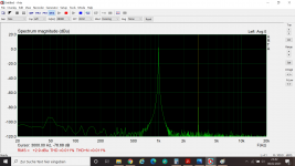
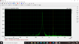
Whilst measuring distortion and playing with P3 I found that at high levels the distortion on the gain stage goes bonkers. Bias and Offest was adjusted as was P3 for minimum even order harmonics. As I am not an EE I prefer talking in Volts without logarithmic scaling.
I did measure (with or without "R5 grounded"):
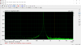
at 1 Volt RMS output of the gain stage: 0,0026 %THD (3rd order)
at 2 V : 0,011 %THD (3rd order)
at 3 V : 0,022 %THD
at 4 V: 4% THD odd order harmonics
I also noticed that some offset can decrease distortion, so I will play a bit with that. I did perform a clipping test and full power before measuring distortion 😀 Maybe this messed something up. The gain is around 10 times Voltage amplification. I did attach the THD measurements (loop soundcard, 1 V Outout, 2V, 3V, 4V)
Can somebody with a little experience please comment on my findings? Thank you very much.
Ozo
I could use some advice with my BA-3B regarding the gain stage.
I just finished my first monoblock and it "works" magic smoke still in the circuit and it does plays music.
Whilst measuring distortion and playing with P3 I found that at high levels the distortion on the gain stage goes bonkers. Bias and Offest was adjusted as was P3 for minimum even order harmonics. As I am not an EE I prefer talking in Volts without logarithmic scaling.
I did measure (with or without "R5 grounded"):
at 1 Volt RMS output of the gain stage: 0,0026 %THD (3rd order)
at 2 V : 0,011 %THD (3rd order)
at 3 V : 0,022 %THD
at 4 V: 4% THD odd order harmonics
I also noticed that some offset can decrease distortion, so I will play a bit with that. I did perform a clipping test and full power before measuring distortion 😀 Maybe this messed something up. The gain is around 10 times Voltage amplification. I did attach the THD measurements (loop soundcard, 1 V Outout, 2V, 3V, 4V)
Can somebody with a little experience please comment on my findings? Thank you very much.
Ozo
Attachments
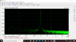
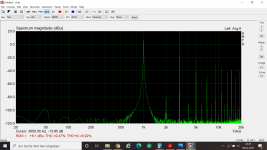
first, you need to keep fundamental at -10dbfs all the time (for all tests) , using some attenuator prior to sound card input
there, you most probably have soundcard input saturated
there, you most probably have soundcard input saturated
- Home
- Amplifiers
- Pass Labs
- Burning Amp BA-3b (Balanced)