Notes and Thoughts
This was originally going to be a thread starter, quite a while ago.. but I decided against it. This may spark some ideas and/or give some people a good chuckle. I started thinking about building a Burning Amp about a year ago. When I read threads from end-to-end, I copy and paste bits and pieces into note files for when I start "really" considering a build.
Here are my notes ... so far... I also do things like put together wiring diagrams like I previously posted. It helps me keep my head straight for things that I've "learned", but aren't yet second nature or even intuitive.
Enjoy! 😀
Attachments
Enjoy! 😀
I did!
I only have one comment on one question you posed:
What would be “better” sonically with my speakers; 12 devices at 0A25 per channel, 12 devices at 0A5 per channel, or 24 devices at 0A25 per channel? I could potentially find out. Initial thoughts are that each is reasonable.
I've been reading/thinking about the effect of the number output devices, and I ran across these quotes (click the blue squares for context):
The F4 gives about the same distortion numbers balanced
or not for any given wattage short of just below the SE
clipping point.
You can get lower distortion yet by:
1) decreasing the Source resistors (more careful matching
reuired for that)
2) More bias (more sinking)
3) more devices (more devices...)
😎
1 and 3 will increase the DF.
Of course, NP's comments on the BA-2 output stage:
You can certainly build this amplifier with fewer output devices as mentioned earlier. It will alter the spectral balance slightly – more outputs tends to put a little more emphasis on the bottom end, and fewer tends to brighten the top. At least this is how you will tend to perceive it. I leave it to you to try this if you like, but I think the direction you would want to go is 2-3 pairs, as we already have overkill with 4.
I have shown a recommended value for the output stage bias at 250 mA / device which is only about 6 watts per device with a +/-25 volt supply. If you have enough heat sinking, you can consider as high as 30 watts per device, allowing the reliable use of fewer devices.
If you decide to higher, remember that Mosfets are better at higher current until they catch fire and fulfill the promise of the amplifier's name.
Another relevant quote:
As I have indicated, when you actually compare the distortion performance of single versus parallel devices, the performance is more a function of the total bias than that of any given device.
There are a number of reasons why that XA30.5 uses ten devices in parallel instead of one:
1) The Zen operates with a much higher impedance seen by the Gate of the Mosfet. In that case, bandwidth will become more limited as you parallel devices due to Cgd. If you want to parallel devices on the Zen, you will want to lower the input and feedback loop impedance or otherwise lower the Gate impedance with a driver or buffer.
2) Idle dissipation. No way am I sending an amplifier into the field with a Mosfet dissipating 50 watts.
3) Thermal modulation. There is lower thermal variation over the operating load line with more devices. Small, but real point.
4) Current capacity. The Zen is short proof (and limited into low impedances) by the constant current source biasing. It simply will not deliver high currents. The XA30.5 is designed to deliver 30, 60, 120, and 240 watts into 8, 4, 2, and 1 ohms until the fuse blows or the thermal switch triggers.
5) Sound. An XA30.5 with fewer devices sounds thinner and has less control than the larger XA amplifiers. Since we want a "family similarity" sonically, we use more devices than absolutely necessary.
6) Convenience. I already have nice output stage boards and heat sinks left over from the XA60.5 development. Being a monoblock, the XA60.5 uses 40 output devices per channel.
7) I love lots of hardware in my output stage. Doesn't everybody?
😎
Another thing that I've observed in LTSpice is that 5 parallel pair at the same total bias as a single pair dramatically improves distortion performance when the amp transitions to class AB into low impedances.
On this point:
If you operate the total group at a few hundred mA, that will be adequate, since at that current level the transconductance of the group as a whole is adequate, and that is what counts for crossover distortion, whether the amplifier is a 50W or 1KW unit.
Note that this comment is purely in the context of class AB operation, hence the low bias number. However, if the transconductance as a group decreases crossover distortion, then more devices = better performance once the class-A bias is exceeded. While to some extent the transconductance does increase with the bias level, adding more devices piles on the transconductance while also offering better thermal advantages (spreading out heat, lower junction temps, etc.). If you have a balanced amplifier, your voltage swing will be more than adequate; in order for the current output to keep up at the highest levels, you might see a lot of AB action.
By way of illuminating this further, some of the best numbers
came from the X600, which did not operate the output stage
in a loop, ran a 2.5A Class AB bias, and of course had no
EC circuit. It measured .01% at 100W.
It did, however, benefit from 12 devices in parallel.
😎
Last edited:
Another quote pertaining to the Aleph 5:
The Aleph 5 uses the output transistors for current AND voltage gain, so it might be a little different context - this post appears to suggest that a source follower application would be less sensitive to the distortion caused by lower bias, but I'm not sure.
Another on the XA30.5:
As a rule, the higher bias figures per device are desirable, and you could optimally look for 1 amp bias per device with supplies at +-25 to 30 volts or so. At the same time, paralleling devices at somewhat lower bias can give you greater transconductance, and this was chosen in designs like the Aleph 60 as it gives more bottom end control.
The Aleph 5 uses the output transistors for current AND voltage gain, so it might be a little different context - this post appears to suggest that a source follower application would be less sensitive to the distortion caused by lower bias, but I'm not sure.
Another on the XA30.5:
The downside of paralleling devices is that the capacitance
increases, but this is not as much of a problem as you might
think, as the primary capacitance is the Cgs. Cgs is charged
by the variation in Vgs, but that variation is inversely proportional
to the transconductance - so the Cgs currents do not scale with
parallel devices.
As a practical matter, output stages with parallel devices do
not particularly suffer increased capacitance in ordinary applications.
The upside is obvious. If you can afford to dissipate heat,
parallel devices will increase the transconductance and linearity
at the cost of high bias current.
The XA30.5 amplifier is rated at 30 watts into 8 ohms, but it
uses 20 (X 150 watt) output devices per channel and is biased
at 100 watts/ch or so. The result is respectably fast and linear.
😎
Last edited:
Fantastic additional information! Thank you, so much. 
One of the things that has puzzled me, as many things do, is Damping Factor. Initially, when I put my very first First Watt clone "up against" a commercial Class A/B monster - I noticed a change in bass. I gravitated straight to another First Watt amp with the highest DF in the table of specs, to see if it solved my "problem". It did not, but maybe I did not have "enough" current. One of the amps I love the most has a "low" damping factor. Go figure....
I have not found a direct correlation in my perception of the "impact" / "tightness" of bass with my speakers based on DF alone. When I was wondering why certain amps in the FW family seemed to have more "punch" (last nebulous term, I promise) with my speakers - I couldn't find any single contributor. However, to me and my ears, with my speakers - I notice a difference that has me running down a rabbit hole - albeit a very fun one - of more current and higher DF in various combinations. So, this is incredible information to bolster my confidence that I'm not barking up the wrong tree.
tl;dr - That's why I want to try various combinations with my speakers to see how things pan out. The versatility of the FW / BA builds is just incredible. Right now, I'm going with MORE CURRENT/MORE DEVICES/MORE BIAS - in a staged approach. It may be a fruitless endeavor as far as real, measurable results, but I know I'm gonna have a kick butt set of monoblocks in one configuration or another that will make me grin from ear to ear.... and I might even learn a thing or two. And... since we have to social distance, my neighbors can hear great tunes at their house too. Everybody wins.
😀 😀 😀
Edited to add - Now where's my link to the El Pipe-O article
Last edited:
I've made a bit more progress laying out the chassis and planning for the different iterations. I decided (perhaps foolishly) to go with the 0R22 source resistors.
My matches were tight (I know my measurement is not accurate to within 4 significant digits, but... they were very stable.
Ns - 12 Low 4V097 : High 4V157.
Ps - 12 Low 4V290 : High 4V303 - The Ps were incredibly consistent.
If the 0R22 are ill advised.... I should know soon enough. I'll measure across each source resistor to check for consistency and bring the bias up slowly.
For now - I'm confident they should be fine. The 3Ps and 3Ns within each channel are within a few mV.
I am starting with one board per channel and doing the BA-3 "std" to check everything out and listen for a bit. Then comes the fun of experimentation and switching to monoblocks (most likely at least a few weeks or even more).
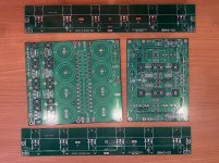
Here is what I came up with for mounting 12 devices on the sinks. Should be no problem to put the bias board on the "higher" of the two. A bit of a pain to move it once I change layouts, but I think it should be clean. No remote wiring etc. Any thoughts are appreciated. I am still on the fence. Is this nuts... ill advised... genius? I may have seen it somewhere, but I truly can't recall. If I am "remembering someone else's solution" I'll gladly give them credit.

Onward we go... Becoming more of a "fearless amplifier builder", but man... 😀 😀
Edited to add - just in case... obviously the pic shows a MOSFET that won't be used. It was a sacrifice from learning to match devices a while ago. I keep it for test fits etc. It's a Fairchild, and I marked it so I wouldn't mix it up with good parts. The MOSFETs on the "left" are shown floating, but when I soldered them into place - I had the ceramic pads installed and did it properly. I was only experimenting with ideas for fit before I put on the bias board.
My matches were tight (I know my measurement is not accurate to within 4 significant digits, but... they were very stable.
Ns - 12 Low 4V097 : High 4V157.
Ps - 12 Low 4V290 : High 4V303 - The Ps were incredibly consistent.
If the 0R22 are ill advised.... I should know soon enough. I'll measure across each source resistor to check for consistency and bring the bias up slowly.
For now - I'm confident they should be fine. The 3Ps and 3Ns within each channel are within a few mV.
I am starting with one board per channel and doing the BA-3 "std" to check everything out and listen for a bit. Then comes the fun of experimentation and switching to monoblocks (most likely at least a few weeks or even more).
Here is what I came up with for mounting 12 devices on the sinks. Should be no problem to put the bias board on the "higher" of the two. A bit of a pain to move it once I change layouts, but I think it should be clean. No remote wiring etc. Any thoughts are appreciated. I am still on the fence. Is this nuts... ill advised... genius?
I may have seen it somewhere, but I truly can't recall. If I am "remembering someone else's solution" I'll gladly give them credit.Onward we go... Becoming more of a "fearless amplifier builder", but man... 😀 😀
Edited to add - just in case... obviously the pic shows a MOSFET that won't be used. It was a sacrifice from learning to match devices a while ago. I keep it for test fits etc. It's a Fairchild, and I marked it so I wouldn't mix it up with good parts. The MOSFETs on the "left" are shown floating, but when I soldered them into place - I had the ceramic pads installed and did it properly. I was only experimenting with ideas for fit before I put on the bias board.
Last edited:
If you have a problem with that layout it’s going to be very, very difficult to remove any devices. Make sure you have a fender washer and split washer since you’ll never be able to snug them up if they thermal themselves loose.
Personally, I’d try to come up with a different configuration.
Personally, I’d try to come up with a different configuration.
I've made a bit more progress laying out the chassis and planning for the different iterations. I decided (perhaps foolishly) to go with the 0R22 source resistors.
My matches were tight (I know my measurement is not accurate to within 4 significant digits, but... they were very stable.
Ns - 12 Low 4V097 : High 4V157.
Ps - 12 Low 4V290 : High 4V303 - The Ps were incredibly consistent.
If the 0R22 are ill advised.... I should know soon enough. I'll measure across each source resistor to check for consistency and bring the bias up slowly.
For now - I'm confident they should be fine. The 3Ps and 3Ns within each channel are within a few mV.
I am starting with one board per channel and doing the BA-3 "std" to check everything out and listen for a bit. Then comes the fun of experimentation and switching to monoblocks (most likely at least a few weeks or even more).
Here is what I came up with for mounting 12 devices on the sinks. Should be no problem to put the bias board on the "higher" of the two. A bit of a pain to move it once I change layouts, but I think it should be clean. No remote wiring etc. Any thoughts are appreciated. I am still on the fence. Is this nuts... ill advised... genius?
View attachment 840627
Onward we go... Becoming more of a "fearless amplifier builder", but man... 😀 😀
Edited to add - just in case... obviously the pic shows a MOSFET that won't be used. It was a sacrifice from learning to match devices a while ago. I keep it for test fits etc. It's a Fairchild, and I marked it so I wouldn't mix it up with good parts. The MOSFETs on the "left" are shown floating, but when I soldered them into place - I had the ceramic pads installed and did it properly. I was only experimenting with ideas for fit before I put on the bias board.
I'm a little unclear (situation normal) about why you are double stacking those boards? You spoke earlier about a transformer not being sufficient for some iterations of BBA3 you had in mind.
Which leads me to wonder are you going for a version with 12 mosfets per side?
According to Nelson's writing above, its a good idea given enough heatsink.
Or, lower rails plus more outputs plus more bias...
Anyway, just wondering. BTW, in the REW/focusrite world, not too far back, I believe Meper? in the BA3 as preamp build thread goes through his setup of focusrite measuring protocol in pics and text.
A lot of folks added some nice ideas in a thread I had quite a while back "P3 adjustment for the average hobbiest" or something similar.
Russellc
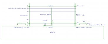
Alternatively -
Thoughts?
(I didn’t draw the standoffs because I’m lazy)
Thoughts?
(I didn’t draw the standoffs because I’m lazy)
Attachments
Last edited:
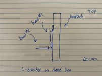
Mount the FET's top side at right angles to the PCB, place the PCB's back to back on the heatsink, use spacers between PCB's & a (hand made) L bracket to fix to the heatsink (use the 4 holes in the middle).
Thread thick copper wire between the O/P 1 bias O/P2 PCB's, I found it a handy way to mounted the board, seemed to work well enough for me.
PS, form loops at the top end of the copper wire, it makes a nice little solder connection for the wiring.
Thread thick copper wire between the O/P 1 bias O/P2 PCB's, I found it a handy way to mounted the board, seemed to work well enough for me.
PS, form loops at the top end of the copper wire, it makes a nice little solder connection for the wiring.
I'm a little unclear (situation normal) about why you are double stacking those boards? You spoke earlier about a transformer not being sufficient for some iterations of BBA3 you had in mind.
Sorry if I was unclear - Wowbagger had asked re: why I was running the PSUs in parallel for (what will be soon) a balanced build. The reason was that one of the 400VA donuts won't be enough for running 12 per side (potentially). So, I am using two for an effective 800VA supply.
Which leads me to wonder are you going for a version with 12 mosfets per side?
Yep, at some point, I just gotta try - so I'm planning ahead.
According to Nelson's writing above, its a good idea given enough heatsink. Or, lower rails plus more outputs plus more bias...
Exactly. I attached a long-ish .pdf with some thoughts. Wowbagger added some additional thoughts and quotes that help confirm that my various iterations should be fun. Basically, from my early math - I'll run out of heatsink before I run out of bias / devices, but 24 devices at 0A25ish should be okay with 4 heatsinks and 800VA. If not, then I'll find out soon enough.
Anyway, just wondering.
Me too... I just wonder... and wonder... 😀
BTW, in the REW/focusrite world, not too far back, I believe Meper? in the BA3 as preamp build thread goes through his setup of focusrite measuring protocol in pics and text.
Thanks! I'll check it out! Right now, I feel like my process is fine, but the software is giving me a fit. Every time I close it down and repeat my settings exactly as I had them... it goes wonky. Time for a fresh install. Also... never discount user error!
A lot of folks added some nice ideas in a thread I had quite a while back "P3 adjustment for the average hobbiest" or something similar.
Russellc
I did see that thread.
6L6, Wowbagger, and Itsmee - Thank you for the great ideas re: mounting!!!! I'm not ready to do it yet. However, now that I've got a few ideas, I know I can tackle it later without taking drastic measures.
Itsmee - I dug back in the thread and in the "Pictures" thread. Did you share a picture on the forum? If so, could you point me toward it or post one, please. I think I understand what you've described - but my spatial skills have gone sideways. 😀
Edited to add - similar to this, but with an L-bracket in the middle and with the bias board connected per your description??
https://www.diyaudio.com/forums/pass-labs/142055-burning-amplifier-ba-1-a-28.html#post3324219
Edited to add - similar to this, but with an L-bracket in the middle and with the bias board connected per your description??
https://www.diyaudio.com/forums/pass-labs/142055-burning-amplifier-ba-1-a-28.html#post3324219
Last edited:
The link didn't take me to a post with a pic.
Sorry, didn't take any photos, and the chassis is in bits becoming something else.
Hope the bad drawing makes it clear.
Edit, I used M3 studding and some nuts for the spacers.
Sorry, didn't take any photos, and the chassis is in bits becoming something else.
Hope the bad drawing makes it clear.
Edit, I used M3 studding and some nuts for the spacers.
Attachments
Last edited:
Apologies for the dud link. It was intended to go to post #279 in the BA-1 thread. I checked the link and it works on my end, but who knows?
More importantly, thank you for taking the time on the superb diagram! Much appreciated! I have a very high confidence I will do this with the BA-1 output stage. Sadly I had already soldered the MOSFETs on one set of boards for the BA-2 output stages (two boards of the four) parallel with the boards. Removing and reorienting them may be a challenge I'm not ready for. I'll be sure to post pics when I get to the BA-1 output stage and give credit where credit is due if I'm able to pull it off.
More importantly, thank you for taking the time on the superb diagram! Much appreciated! I have a very high confidence I will do this with the BA-1 output stage. Sadly I had already soldered the MOSFETs on one set of boards for the BA-2 output stages (two boards of the four) parallel with the boards. Removing and reorienting them may be a challenge I'm not ready for. I'll be sure to post pics when I get to the BA-1 output stage and give credit where credit is due if I'm able to pull it off.
It may be because I have my preference setting to 50 posts per page.
And no problem, you'll pay it forward when you can 😉
And no problem, you'll pay it forward when you can 😉
Itsmee - Definitely!
And here's the first step in the journey - the BA3. Up and running! 😀
https://www.diyaudio.com/forums/pas...r-illustrated-build-guide-28.html#post6193103
Post #273 in the BA3 Build Guide Thread.
Once again - thanks to Papa, 6L6, Zen Mod, and the countless others that have helped and sparked ideas along the way. As I progress from Burning Amp to a pair of Flaming Goofball Amps - I'll post the progression.
BA3B for beginner
Hi,
I'd like to build a couple of F4 monoblock and use this balanced preamplifier.
First of all I'm not an expert as you and I have some difficult to read and write in english. For me it's difficult read the whole thread also considering that I'm able to build but I'm not able in electronic...
First of all I think that to build a BA3B I must build two BA3 and use a balanced potentiometer.
Right?
There are some schematics regarding wiring the boards and connection?
Thank you!!!
Hello. There are a few threads on using the BA-3 as a pre-amplifier. This thread is generally concerning building the full input stage and output stage as a power amplifier.
I would consider trying asking in this thread for some ideas. I think you'll enjoy it very much. I am not sure if there is a dedicated thread for the balanced build of the pre-amp. However, I think you'll find everyone helpful and the process for using one board for each phase quite easy.
The BA-3 as preamp build guide
Good luck with your build.
- Home
- Amplifiers
- Pass Labs
- Burning Amp BA-3b (Balanced)