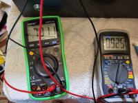
Today I noticed something odd with my BA-3B monos connected via XLR to my Aleph P1.7 pre whilst performing some THD measurements on the pre:
When the BA-3bs are turned off but still connected to the P1.7 the output of the P1.7 already starts to distort at 120mV output voltage (measured single ended) as if it was overloaded. When the BA-3bs are turned on or disconnected everything is hunky dory and distortion stays at or below 0,02% up to 5V (measured single ended) output of the pre. So far I checked the input DC resistance of the BA-3bs and measured the expected 48k. In a next step I´ll measure the current at 200mV or so.
Edit: The XLR cables are 5 meters
Has anybody experienced something odd like that or has some idea what might be going on?
It is not totally academic as I want to use the single ended outputs of the pre whilst the monoblocks are connected and turned off.
Many thanks
Ozo
Attachments
Last edited:
sole explanation, if there are just input gates and you didn't put any addendum on amp inputs ......... JFet gate can be (current) hungry, if rest of the JFet isn't energized, to follow gate's modulation
remember - in almost each JFet datasheet, besides finding D-S current figure, there is also Gate current figure
though, that needing systematic confirmation, I did never exactly thought about that thus never checked
remember - in almost each JFet datasheet, besides finding D-S current figure, there is also Gate current figure
though, that needing systematic confirmation, I did never exactly thought about that thus never checked

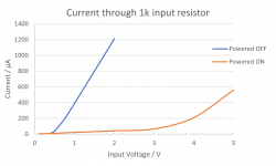
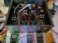
Mighty ZM is right indeed - thank you! I have measured the current draw on the 1k Input resistor using a board stuffed with Linear Systems JFETs that I had around in the ON and OFF state. The result shows the fact very clearly. On the Toshiba JFETs in my system the blue curve is probably shifted to even lower onset voltages. I will consider changing the input resistor to 10 or 20k and compensate the gain loss in the Aleph P or something else...JFet gate can be (current) hungry, if rest of the JFet isn't energized, to follow gate's modulation
Thanks again mighty one!
Attachments

a little smidge here and there makes you more human, to which mere mortals can relate a little better.

Mighty Zen Mod is, as always, our tutor! The Aleph P is also a current source output stage. I believe the output impedance is just over 2k ohms if memory serves. If you are using it as designed with the attenuation on the output side then when you go to drive a low impedance load with little or no attenuation you can get output clipping.
Indeed - I use it as intended with the attenuator on the output. I always thought JFET gates were like MOSFET gates - just a capacitor with negligable leakage current. Today I learned, they can draw too much current for my Aleph P, if powered off.If you are using it as designed with the attenuation on the output side then when you go to drive a low impedance load with little or no attenuation you can get output clipping.
I´ll probably refrain from changing the input Resistor on the BA-3 to 10k, as it might slow the circuit down. It only means I cannot connect my headphone amp to the Aleph P´s output whilst he BA-3 is also connected and powered off.

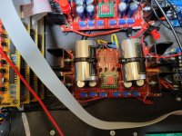
Finally I replaced the IRFP9240s from IRF with Harris parts. They cut the distortion at least in half also in balanced operation. As I measured first and listened second I do not know how much bias I had, but it sounded a good bit smoother. It was 2 days of work, but totally worth it as I can sleep better now. The parts can still be had from Rochester: IRFP9240. I had 100 pcs. and the deviation in Vgs was very small.
Attachments

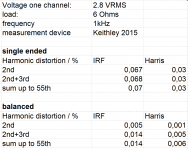
FWIW, Rochester also had Harris 240s if you want them to visually match:

(There's no sound difference on the 240s, so this is purely for visual aesthetics.)
(There's no sound difference on the 240s, so this is purely for visual aesthetics.)

Hello.
I build the BA-3 balanced.
3 of the 4 parts of the BA-3b I can set without problems.
The last part I can not set to 1V waste via R10+R11.
P1 max turned up = 0.3642V, P2 max. = 0.604V, P3 in the middle.
P1 max. turned up = 0.7911V, P2 max. = 0.925V, P3 turned to the right.
If I twist P1, the value of P2 also changes.
If I twist P2, nothing changes to the value of P1.
The values of the pots are ok.
Is possibly Q1 / Q2 defective.
Could I please get a tip where to look.
Greetings Dirk
Attachments
What parts are you using for Q3 and Q4? Brand?
What value pots for P1 and P2?
Edited to add - Found the relevant post / citation. This is why I ask.
"In this schematic note that the Mosfets types are not shown. The suggested pieces are Toshiba 2SK2013 / 2SJ313 (hard to find) and Fairchild FQP3N30 / FQP3P20 (easy to find). I’ve built using both types and can tell no real difference between the Toshiba and the Fairchild. If using Fairchild, use 1K pots for P1, P2. These Mosfets do not need to be matched."
"https://www.diyaudio.com/community/threads/ba-3-amplifier-illustrated-build-guide.258301/"
Last edited:
Do both channels behave similarly?
Did you try to bias the front end prior to adding the DIP switch modification for moving from SE to Balanced?
Inputs shorted?
Can you clarify what you are measuring when you refer to below?
If I twist P1, the value of P2 also changes.
If I twist P2, nothing changes to the value of P1.
Are you saying that when you twist P1, the Voltage reading across both R10 and R11 changes, but when you twist P2 only the value across R10 changes?
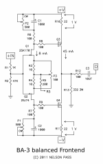
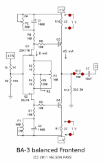
Can you please tell us where you have your 3 sets of DMM probes, please. I cannot see in the picture. Perhaps show on the schematic.
Did you try to bias the front end prior to adding the DIP switch modification for moving from SE to Balanced?
Inputs shorted?
Can you clarify what you are measuring when you refer to below?
If I twist P1, the value of P2 also changes.
If I twist P2, nothing changes to the value of P1.
Are you saying that when you twist P1, the Voltage reading across both R10 and R11 changes, but when you twist P2 only the value across R10 changes?
Can you please tell us where you have your 3 sets of DMM probes, please. I cannot see in the picture. Perhaps show on the schematic.
" Do both channels behave similarly?" All 3 different channels are ok.
" Inputs shorted?" Entrances open.
" Did you try to bias the front end prior to adding the DIP switch modification for moving from SE to Balanced?" Frontend not preloaded, BA is in Fe mode
" Are you saying that when you twist P1, the Voltage reading across both R10 and R11 changes, but when you twist P2 only the value across R10 changes?" That's right
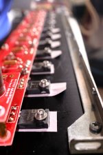
"Can you please tell us where you have your 3 sets of DMM probes, please. I cannot see in the picture. Perhaps show on the schematic." Sodes above R10, R11 and 12
measured by the red dots
" Inputs shorted?" Entrances open.
" Did you try to bias the front end prior to adding the DIP switch modification for moving from SE to Balanced?" Frontend not preloaded, BA is in Fe mode
" Are you saying that when you twist P1, the Voltage reading across both R10 and R11 changes, but when you twist P2 only the value across R10 changes?" That's right
"Can you please tell us where you have your 3 sets of DMM probes, please. I cannot see in the picture. Perhaps show on the schematic." Sodes above R10, R11 and 12
measured by the red dots
Attachments
- Home
- Amplifiers
- Pass Labs
- Burning Amp BA-3b (Balanced)